80 Detail program description - Base setup models | Winged models
then activate the option with a brief tap on the center
SET button of the right touch pad.
Stick mode
Module
1
bind
bind
n/a
n/a
HoTT
SET SET SEL SET
Rcv Ch Map R16 R08
n/a
n/a
RF transmit on
BASIC SETTING,MODEL
The right selection keys can now be used to choose
between OFF and ON. Another tap on the center
SET
key of the right touch pad will conclude the entry.
Range test
The built-in range test reduces transmission power
to an extent that a functional test can be carried out
even within a distance of less than 100 m.
Perform a range test on the Graupner HoTT system
according to the following instructions. If necessary,
have someone assist you in carrying out the range test.
Preferably, the receiver already bound to the 1.
transmitter should be installed into the model in its
intended position.
Switch remote control on and wait for the green 2.
LED to light up on the receiver/s. Now servo
movements can be observed.
Place the model on a level surface (pavement, 3.
low-cut grass or bare ground) such that receiver
antennas are at least 15 cm above ground level.
It may be necessary to put something under the
model to raise it up enough for this.
Hold the transmitter at hip level and at some 4.
distance from one's body. Do not point the
antenna directly at the model but rather turn and/
or kink the antenna's end so that it is oriented
vertically during the test.
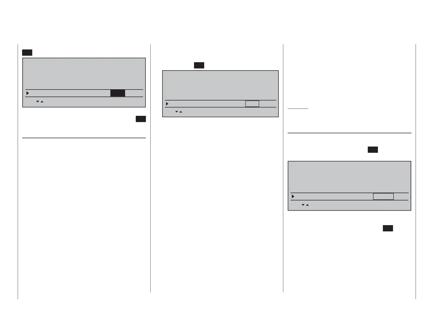
If necessary, use the 5. cd selection keys of the left
or right touch pad to reach the "RF range test" line
in the menu then start range test mode with a tap
on the center
SET key of the right touch pad.
Module
bind
bind
n/a
n/a
HoTT
SET SET SEL SET
Rcv Ch Map R16 R08
n/a
n/a
RF transmit on
RF range test 99s
BASIC SETTING,MODELL
When the range test has been initiated,
the transmitter's transmission power will be
signifi cantly reduced and the LED just to the right
of the main switch on the transmitter, marked RF,
will begin to blink; this will also be accompanied by
acoustic tones. At the same time, the timer in the
transmitter's display will start counting down and
every 5 seconds a two-frequency tone will sound.
Five seconds prior to the end of the range test
a three-frequency tone will sound once every
second. After expiration of the range test's 99th
second the transmitter will again be switched to
full output power and the LED just to the right
of the main switch on the transmitter will again
illuminate constantly.
Move away from the model while manipulating 6.
the joysticks during this timespan. If you notice an
interruption anytime while still within a distance of
about 50 m, try to reproduce this malfunction.
If there is a motor in the model, it may be necessary 7.
to switch it on to further check noise immunity.
Continue moving away from the model until 8.
perfect control is no longer possible.
Wait at this distance for the remainder of the test 9.
period with the still-operationally-ready model
to expire. After the range test is ended it should
again respond correctly to all RC controls. If this
is not 100 % the case, do not use the system.
Contact your area's Graupner GmbH & Co. KG
service partner.
Perform the range test before each fl ight and, in 10.
doing so, simulate all servo movements which
also take place during fl ight. The range must
always be at 50 m on the ground in order to
assure safe model operation.
Caution:
Never start the range test on the transmitter
during normal operation of the model.
DSC output
If necessary, use the cd selection keys of the left
or right touch pad to switch to the "DSC Output" line
then, with a brief tap on the center
SET key of the
right touch pad, activate the value window:
SET SET SEL SET
Rcv Ch Map R16 R08
n/a
n/a
RF transmit on
RF range test 99s
DSC Output PPM10
BASIC SETTING,MODEL
Now you can use the right selection keys to choose
between four types of modulation "PPM10", "PPM16",
"PPM18" and "PPM24". Touch the center
SET key of
the right touch pad again to complete the entry.
This choice primarily infl uences the maximum
number of control channels which can be attached to
the DSC (direct servo control) socket, and thus also
available to a fl ight simulator or teacher/pupil system.
By selecting "PPM10" this will be control channels
1 … 5, for "PPM16" channels 1 … 8, for "PPM18"
channels 1 … 9 and for "PPM24" channels 1 … 12.