43
Commissioning the transmitter
Universal/EUROPE mode be used IN FRANCE.
As many as 16 servos can be attached to the •
standard receiver included with the
mc-20
HoTT 2.4 Set. The specifi c receiver included
in the set has already been bound to the set's
transmitter at the factory.
In order to achieve the greatest possible
fl exibility but still preclude unnecessary
inadvertent operator errors, control channels
5 … 16 have not been assigned to any
controls. This means that servos connected
by way of these channels will remain in their
middle positions until an operator element
has been assigned. Practically all mixers are
initially inactive for this same reason. More
about this can be found on page 108 (winged
aircraft) or 112 (helicopter models).
The fundamental procedure for initial •
programming of a new model memory location
can be found on page ?? and the programming
examples that begin on page 268.
When the remote control system is switched •
on, being bonded or when making settings,
that the transmitter's antenna is always far
enough away from the receiver's antennas.
If the transmitter's antenna is brought too
close to the receiver's antennas this will cause
receiver over-modulation and its red LED will
illuminate. At the same time the return channel
will drop out and, as a consequence, the fi eld
strength indicator in the transmitter's screen
will be replaced by an "x" and the receiver's
current battery voltage display will show 0.0 V.
The remote control is then in Fail-Save mode,
see page 208, i.e. servos will remain in their
current positions until a new, valid signal
can be received. In such a case, increase
the distance (between the transmitter and
the model containing the receiver) until the
indicators are again "normal".
Transmitter fi rmware updates are carried out either
as described under "FIRMWARE UPDATE / Change
display language" in the section »Secret mode« on
page 33 or as described below with the help of a PC
running a Windows XP, Vista or 7 operating system. This
second method connects the transmitter to the PC via its
5-pole mini-USB interface connector, located behind the
transmitter's left front cover – as viewed from the front –
and, if this method is chosen, it is done at one's own risk.
Current software and information is available in
Internet at www.graupner.de under the Download link
for the given product.
Note:
You will automatically be notifi ed of new updates
per email after registering your transmitter at
https://www.graupner.de/de/service/produktregistrierung.
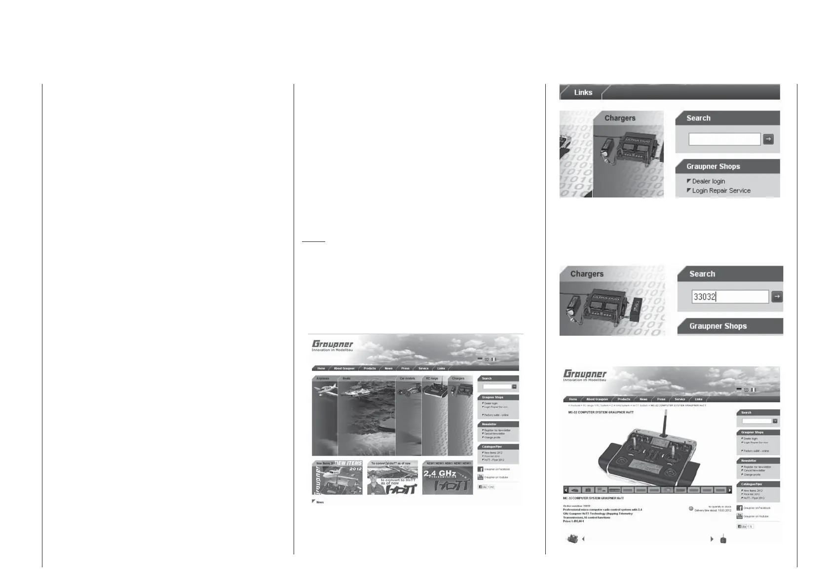
The aforementioned "given product page" is most
easily reached by entering "www.graupner.de" into
your Internet browser's address line then pressing the
ENTER key on your PC or laptop keyboard.
On the so-called "homepage" for Graupner, click on
one of the "fl ags" to switch the website to a language of
your choice, e.g. the British fl ag for English. Afterwards
locate the entry fi eld with the title "Search".
Place the cursor in this fi eld with a mouse click then
enter a search keyword, e.g. the article number
printed on the type plate located on the rear side of
the transmitter.
Another press of the ENTER key on the PC or laptop
will open the sought page:
Transmitter fi rmware updates