179
Detail program description - Helicopter mixer
Please note that the percentage value on the •
"Output" line always relates to the current joystick
position and not to the position of the point.
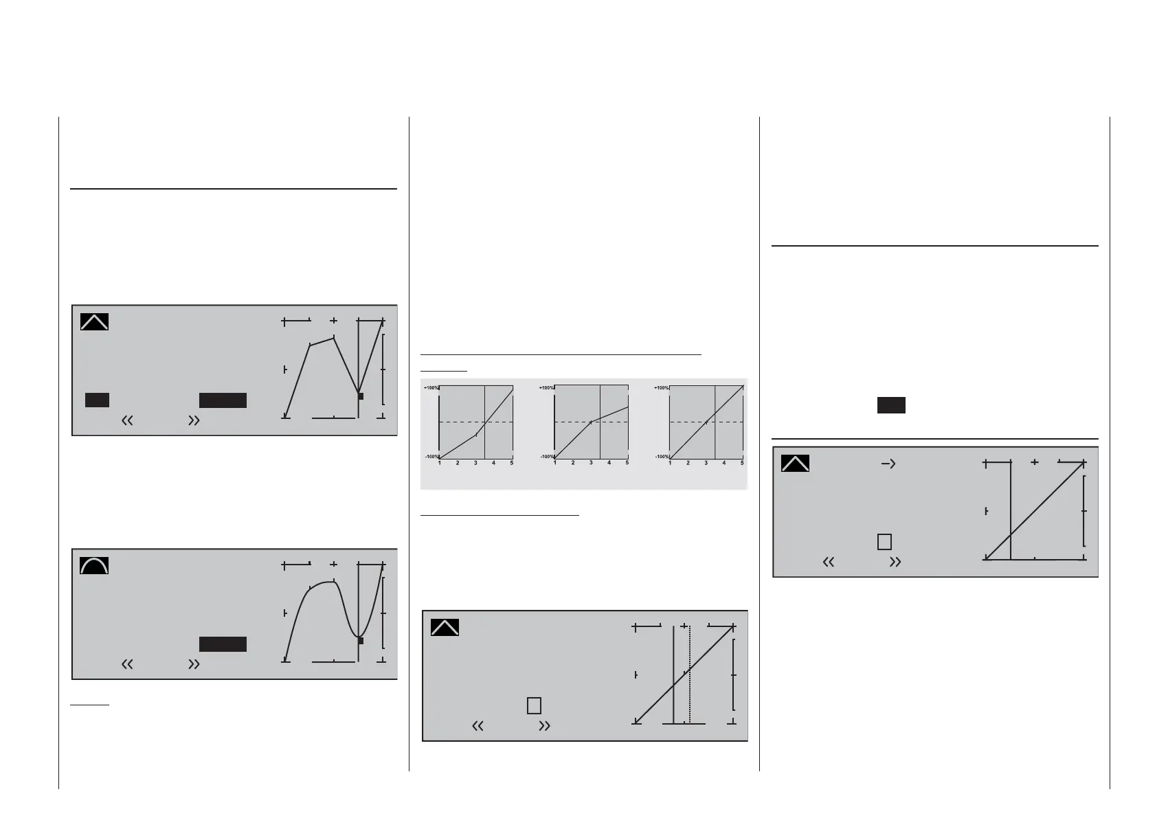
Smoothing the collective pitch curve
In the example below, sample reference points have
been set …
reference point 1 to +50 %,
reference point 2 to +75 % and
reference point 3 to -50 %
… as described in the last section.
Pitch
Curve
off Point
Output
Input +50%
–50%
3
+
–
100
¼ O U T P U T
2
–50%
Normal
1
3
This "jagged" curve profi le can be smoothed
automatically simply by pressing a button.
Do this – from a situation as illustrated – with a brief
tap on the d selection key of the left touch pad. This
will cause a switchover from "(Curve) off" to "(Curve)
on" (or vice versa).
Pitch
Curve
on Point
Output
Input +50%
–50%
3
+
–
100
¼ O U T P U T
2
–50%
Normal
1
3
Notes:
If the joystick does not coincide with the exact •
reference point, please note that the percentage
value on the "Output" line always relates to the
current joystick position.
The fi gures on these pages show control curves •
created only for the purpose of illustration. Please
note, therefore, that the curve characteristics
displayed do not in any way represent real-life
collective pitch curves. A specifi c application
example can be found in the programming
examples on page 312.
The following three graphs show typical 3-point pitch
curves for various fl ight phases, such as hovering,
aerobatics and 3D fl ight.
The vertical bar depicts the current joystick position.
Please note that trim values greater than +100 % and
less than -100 % cannot be presented in the display.
Sample collective pitch curves for various fl ight
phases:
Output
Output
Output
Control travel Control travel Control travel
Aerobatics
3DHover
Notice about marker keys:
If marker keys have been set in the »Basic settings,
model« menu, page 91, touching a key while in
this graph will set a dashed vertical line to show the
position of the C1 joystick at the time the key was
pressed.
Pitch
Curve
off Point
Output
Input 0%
0%
?
+
–
100
¼ O U T P U T
1
0%
Normal
Move the C1 joystick (continuous line) to the marker
line in order to read out the input and output values.
If the marker line, for example, indicates momentary
hovering fl ight and this is to be put exactly in control
center then it is only necessary to transfer the
"output" value of the marker line, in this example, shift
control center to reference point "1".
Erasing reference points
To delete one of the reference points (1 to max. 6), use
the joystick to move the vertical line into the vicinity
of the reference point in question. As soon as the
reference point number and its associated value is
shown on the "Point" line (see screen image above),
following activation of the value fi eld on the "Point"
line now in inverse video with a simultaneous tap on
thecd or ef keys of the right touch pad (CLEAR) it
can be erased. Complete the operation with a brief tap
on the center key
ESC of the left touch pad.
Channel 1 ¼ Throttle (Throttle curve)
Channel 1
Curve
off Point
Output
Input +25%
+25%
?
+
–
100
¼ O U T P U T
+50%
Throttle
Normal
Unlike the »Channel 1 curve« menu, this display is
only associated with the control curve of the throttle
servo, whereas the the "Channel 1 curve" affects all
servos controlled by the throttle/pitch joystick.
Note that the output signal of the "Channel 1
curve" menu thus functions as an input signal for
the throttle curve programmed here: In the graph,
the vertical line is synchronized with the throttle/
collective pitch stick and therefore follows the
current Channel 1 curve characteristic.
The throttle curve can also be defi ned (separately

 Loading...


