-26-
Model G0824 (Mfd. Since 12/16)
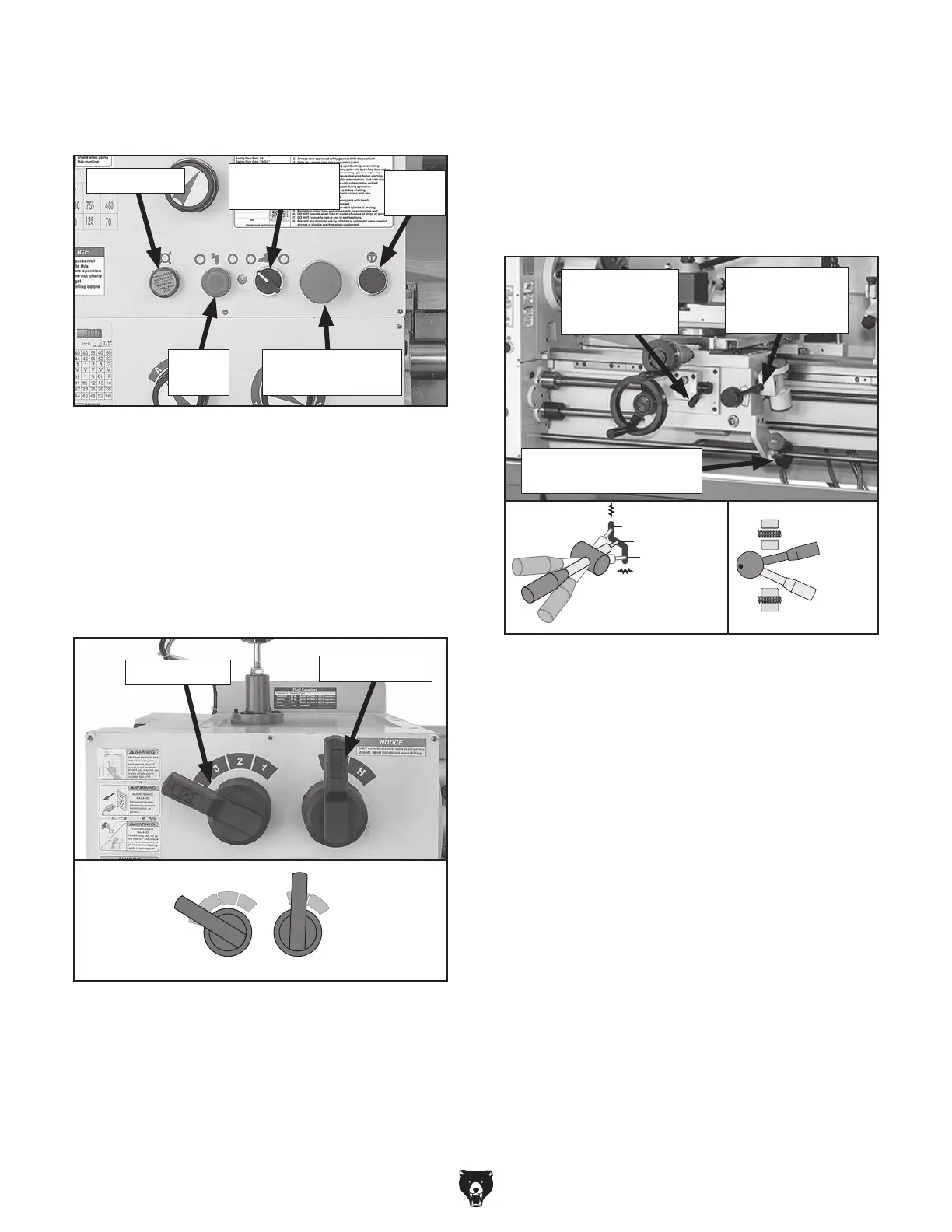
6. To ensure carriage components do not unex-
pectedly move during the following steps,
disengage half nut lever and feed selection
lever (see Figure 26). Rotate carriage and
cross slide handwheels back and forth while
moving levers to verify they are disengaged.
When disengaged, handwheels will turn with
ease.
3.
Push Emergency Stop/RESET button on
control panel (see Figure 24), and point cool-
ant nozzle into chip pan.
7.
Rotate Emergency Stop/RESET button clock-
wise so it pops out. Power light on the control
panel should illuminate.
8.
Push power button, then move spindle lever
(see Figure 26) down to start spindle. The
top of the chuck should turn down and toward
front of lathe.
—
When operating correctly, machine will
run smoothly with little or no vibration or
rubbing noises.
— Investigate and correct strange or unusual
noises or vibrations before operating
machine further. Always disconnect
machine from power when investigating
or correcting potential problems.
Engaged
Half Nut
Lever
Disengaged
Cross Slide
Feed Selection
Lever
Carriage
Spindle Lever
(OFF, Center Position)
Figure 26. Disengaging carriage components.
Figure 24. Control panel buttons used in test
run.
Coolant
Pump Switch
Jog
Button
Emergency Stop/
RESET Button
Power
Button
Power Light
4. Move spindle speed and speed range levers
to L and 4. This will set spindle rotation at 70
RPM (see Figure 25).
Note: In the next step, you may need to rock
the chuck back and forth as you make the
adjustments to cause the gears to mesh.
Figure 25. Spindle speed set to 70 RPM.
Speed
Lever
Set to "4"
Speed
Range
Lever
Set to "L"
1
2
3
4
H
L
Speed Lever
Speed Range
5. Make sure spindle lever is in OFF (middle)
position (see Figure 26) to prevent unex-
pected startup when power is enabled.
Note: You need to pull the lever out (or right)
to disengage the lug in order to adjust the
position.
Feed Lever is
Horizontal
(Disengaged)
Half Nut Lever
is Pulled Up
(Disengaged)
 Loading...