17.49.3 Cascade operation
Cascade operation ensures that the pump
performance is automatically adapted to the
consumption by switching pumps on or off. The
system thus runs as energy-efficiently as possible
with a constant pressure and a limited number of
pumps.
When a twin-head pump is running in constant-
pressure control mode, the second pump head starts
at 90 % and stops at 50 % performance.
All pumps in operation run at equal speed. Pump
changeover is automatic and depends on energy,
operating hours and fault.
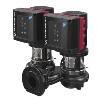
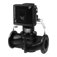
Pump system:
• Twin-head pump.
• Two to four single-head pumps connected in
parallel.
The pumps must be of the same type and size.
Each pump requires a non-return valve in series
with the pump.
Set the control mode to Const. pressure or Const.
curve. In constant curve all pumps will run at the
same time.
This function is available with up to 4 motors installed
in parallel. The motors must be of the same size and
the pumps must be of the same model.
• The performance is adjusted to the demand
through cutting pumps in or out and through
parallel control of the pumps in operation.
• The controller maintains a constant pressure
through continuous adjustment of the speed of the
pumps.
• Pump changeover is automatic and depends on
load, operating hours and fault detection.
• All pumps in operation run at the same speed.
• The number of pumps in operation also depends
on the energy consumption of the pumps. If only
one pump is required, two pumps will run at a
lower speed if this results in a lower energy
consumption.
• If several motors in the system have a sensor,
they can all function as master and take over the
master function if the other motors fail.
17.49.4
"Sensor to be used"
Define the sensor to be used for controlling the pump
system. If a sensor is placed in a way that it is able to
measure the sensor output from all pumps in the
system, for example, in the manifold, then select
"Master pump sensor".
If a sensor is placed on, or across the individual
pumps, for example, installed behind non-return
valves and not able to measure the sensor output
from all pumps, then select "Running pump sensor".
17.49.5
Setting a multipump system
You can set a multipump system in the following
ways:
• Grundfos GO and wireless pump connection
• Grundfos GO and wired pump connection
• Advanced control panel and wireless pump
connection
• Advanced control panel and wired pump
connection..
See step-by-step descriptions below.
Grundfos GO and wireless pump connection
1. Power on both pumps.
2. Establish contact to one of the pumps with
Grundfos GO.
3. Set the needed analog and digital inputs via
Grundfos GO according to the connected
equipment and the required functionality. See
section Assisted pump setup.
4. Assign a pump name to the pump using Grundfos
GO. See section "Pump name".
5. Disconnect Grundfos GO from the pump.
6. Establish contact to the other pump.
7. Set the needed analog and digital inputs via
Grundfos GO according to the connected
equipment and the required functionality. See
section Assisted pump setup.
8. Assign a pump name to the pump using Grundfos
GO. See section "Pump name".
9. Select the "Assist" menu and "Multipump setup".
10. Select the desired multipump function. See
sections Alternating operation, Backup operation
and Cascade operation.
11. Press [>] to continue.
12. Set the time for pump changeover such as the
time at which the alternation between the two
pumps is to take place. This step applies only if
you have selected "Alternating operation, time"
and if the pumps are fitted with FM 300.
13. Press [>] to continue.
14. Select "Radio" as the communication method to
be used between the two pumps.
15. Press [>] to continue.
16. Press "Select pump 2".
17. Select the pump from the list. Use the [OK] or
button to identify the pump.
18. Press [>] to continue.
77
English (GB)