GSI TympStar Pro User Manual
D-0129427 Rev. B Page 45 of 162
The area to the right of the graphic area displays the admittance and pressure meters
along with the results of the tympanogram displayed in a table. The area under the
tympanogram has the parameter buttons for the acoustic reflexes. Up to four acoustic
reflexes may be collected for each screening test. The Screener menu appears at the
bottom of the screen.
Probe Status Indicator
The probe status indicator indicates the
state of the probe and displays messages
regarding the current test. On the left side of the indicator, the two circles will be colored
to match the LED lights on the probe box. The probe may be in the following states:
Hold – ready to continue test
Leak (or possible internal error on the device)
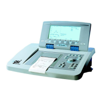
Admittance and Pressure Meters
The admittance meter displays the real
time admittance as it is being recorded
from the probe in the ear canal. The
units are millimhos (mmho). The
current value is displayed at the top left
of the meter.
The pressure meter displays the real time pressure as it is being recorded from the probe
in the ear canal. The units are decapascals (daPa). The current value is displayed at the top
left of the meter.
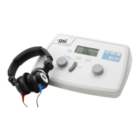
Tympanometry Test Results
The middle right side of the Screener
screen displays the tympanogram results
in a table. The header of the table
indicates the test number and the probe
tone frequency. The Tymp column
displays the tympanogram number, the