GSI TympStar Pro User Manual
D-0129427 Rev. B Page 72 of 162
The individual reflex latency curve is stored to the reflex latency results area under the data
collection graphs when the store icon is pressed. The reflex latency menu bar is under the
results area.
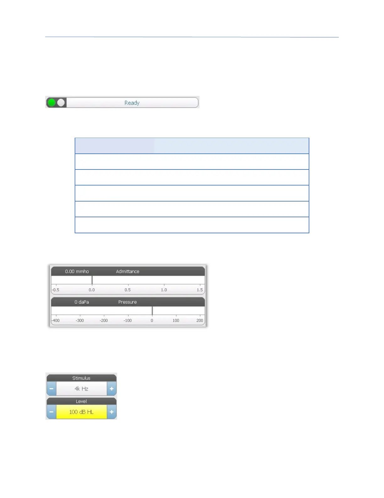
Probe Status Indicator
The probe status indicator indicates the
state of the probe and displays messages
regarding the current test. On the left side of the indicator, the two circles will be colored
to match the LED lights on the probe box. The probe may be in the following states:
Blinking Green Ready
Hold – ready to continue test
Leak (or possible internal error on the device)
Admittance and Pressure Meters
The admittance meter displays the
real time admittance as it is being
recorded from the probe in the ear
canal. The units are millimhos
(mmho). The current value is
displayed at the top left of the meter.
The pressure meter displays the real
time pressure as it is being recorded from the probe in the ear canal. The units are
decapascals (daPa). The current value is displayed at the top left of the meter.
Reflex Stimulus Information
The reflex stimulus information displays the eliciting stimulus
information. The level and stimulus type are controlled from the
buttons on the front panel or the + and – buttons on the sides. If
the stimulus level is set to 100 dB HL or greater, a yellow background
is displayed to caution the user that a high output level has been
selected. The default settings for the reflex latency test are set in the PC Config App.

 Loading...