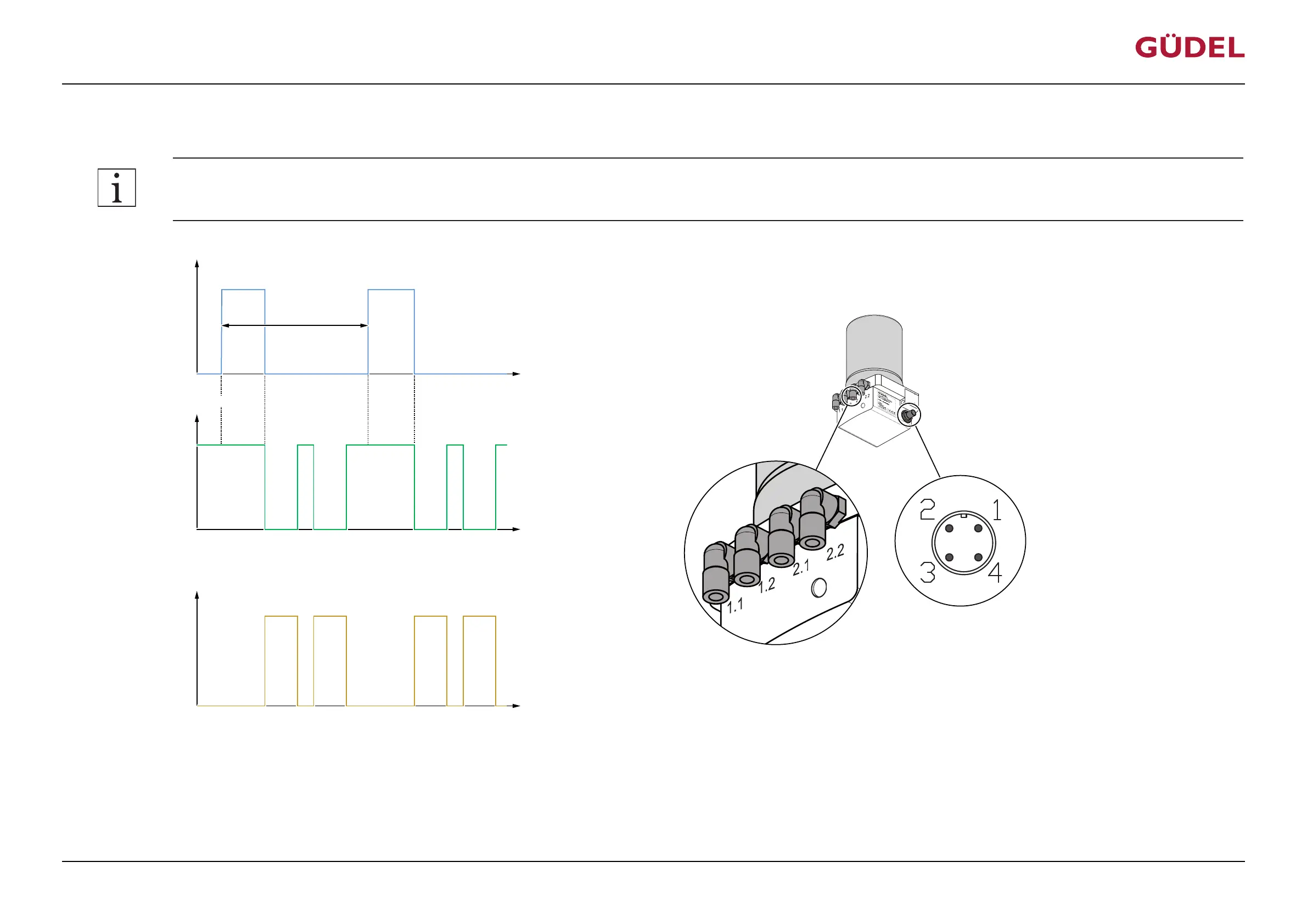
5.5.2.1 Lubrication
The following signal on PIN2 causes the output of 0.16 cm
3
lubricant at each of the four hydraulic outputs:
Accuracy of the impulses (High) on PIN 2: +/- 0.1s!
Input signal PIN 2
Output signal PIN 4
U
U
+24 V
(High)
+ 0 V
(Low)
(Low)
+ 0 V
(High)
+24 V
t
t
8 s 8 s
3 s
7s …
17 s
7s …
17 s
7s …
17 s
7s …
17 s
1.1 or
1.2
2.1 or
2.2
Hydraulic output
2.1 or
2.2
1.1 or
1.2
min. 47s
pause
t
0.16cm³
0.16cm³
0.16cm³
0.16cm³
V
3 s
Fig.5-8 Switching time diagram: Lubrication (normal case)
At the displayed signal on PIN2, all four hydraulic outputs dispense 0.16 cm
3
lubricant. Start of the discharge = output 1.1 or 1.2, then output 2.1 or 2.2. Each hydraulic output is filled with lubricant by
its respective piston. Each piston carries out a lubrication stroke. Per lubrication stroke, 0.16 cm
3
lubricant is discharged in the respective hydraulic output. The output signal on PIN4 is High (20...30
V) during normal operation. During an actual motor run of the lubricating system, the signal switches to Low (+0V). Usually this takes between about 7 and 17 seconds, depending on the length of the
lubrication lines and the viscosity of the lubricant. The signal then switches back to High (+24 V).
CommissioningOPERATING MANUAL Lubrication system FlexxPump4D
9007202674126091_v2.0_EN-US
47