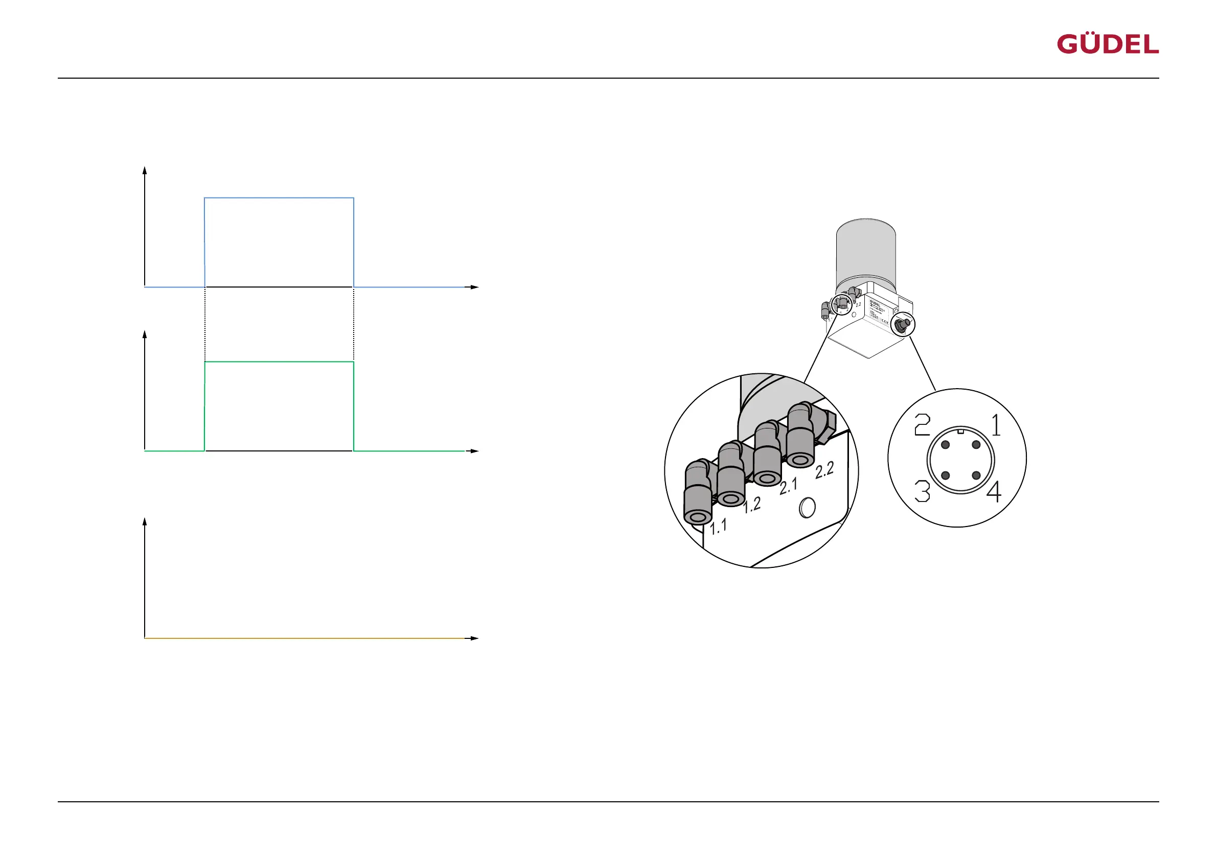
5.5.3.1 Switching on and off
Input signal PIN 1
Output signal PIN 4
U
U
+24 V
(High)
+ 0 V
(Low)
(Low)
+ 0 V
(High)
+24 V
t
t
Hydraulic output
t
V
Fig.5-11 Switching time diagram: Switching on and off
The lubrication system is switched on as long as a constant voltage of +24 V DC is applied at PIN 1. Saved information is lost when the lubrications system is switched off. The output signal on PIN 4 is
High (20...30V) during normal operation. For regular lubricant application, the lubrication system needs to be controlled by a PLC. A pulse rhythm needs to be sent for every lubrication cycle, by
means of a control signal from the PLC.
CommissioningOPERATING MANUAL Lubrication system FlexxPump4D
9007202674126091_v2.0_EN-US
55