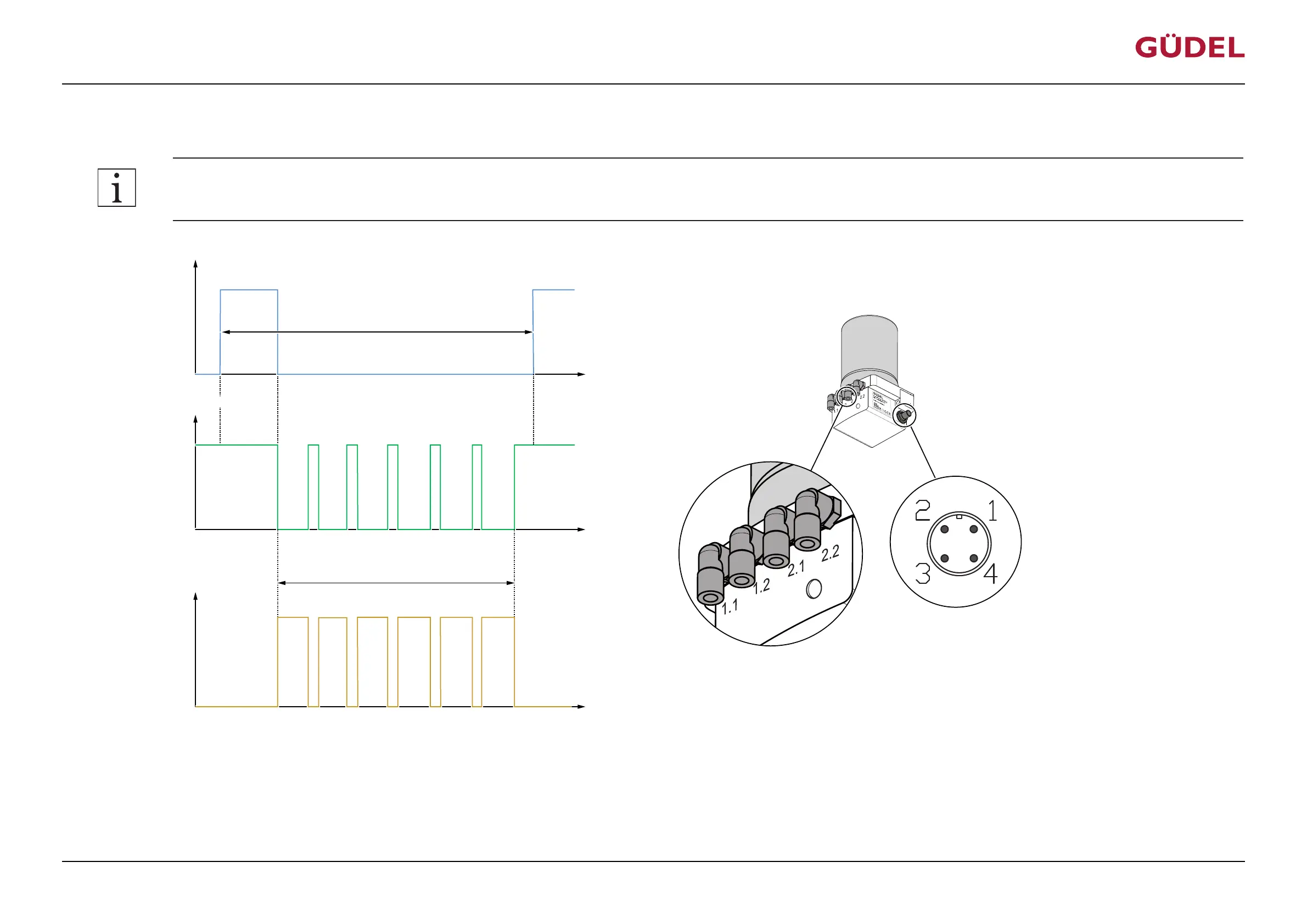
5.5.2.2 Filling lubrication lines / Venting FlexxPump4D
The following signal on PIN2 causes the output of 40 x 0.16 cm
3
lubricant at each of the four hydraulic outputs:
Accuracy of the impulses (High) on PIN 2: +/- 0.1s!
Input signal PIN 2
Output signal PIN 4
U
U
+24 V
(High)
+ 0 V
(Low)
(Low)
+ 0 V
(High)
+24 V
t
t
12 s
3 s
7s …
17 s
7s …
17 s
7s …
17 s
7s …
17 s
1.1 or
1.2
2.1 or
2.2
Hydraulic output
2.1 or
2.2
1.1 or
1.2
t
0.16cm³
0.16cm³
0.16cm³
0.16cm³
V
7s …
17 s
0.16cm³
1.1 or
1.2
Repetition 80x
…
…
3 s
min. 1533 s pause
Fig.5-9 Switching time diagram: Filling lubrication lines / Venting FlexxPump4D
The filling process starts with the displayed signal on PIN2. The filling process takes at least 1533seconds. The filling process has to be restarted after the lubrication system is switched on if it was in-
terrupted by the switching off of the lubrication system. The output signal on PIN4 is High (20...30 V) during normal operation. During an actual motor run of the lubricating system, the signal
switches to Low (+0V). Usually this takes between about 7 and 17 seconds, depending on the length of the lubrication lines and the viscosity of the lubricant. The signal then switches back to High
(+24 V).
CommissioningOPERATING MANUAL Lubrication system FlexxPump4D
9007202674126091_v2.0_EN-US
49