GDS-2000A Series User Manual
138
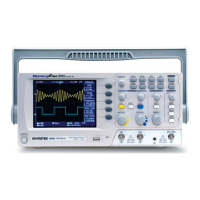
The vertical scale indicator on the
bottom left of the display changes
accordingly for the specific channel.
1mV/div ~ 10V/div (1MΩ). 1-2-5
increments
In Stop mode, the vertical scale setting can be
changed.
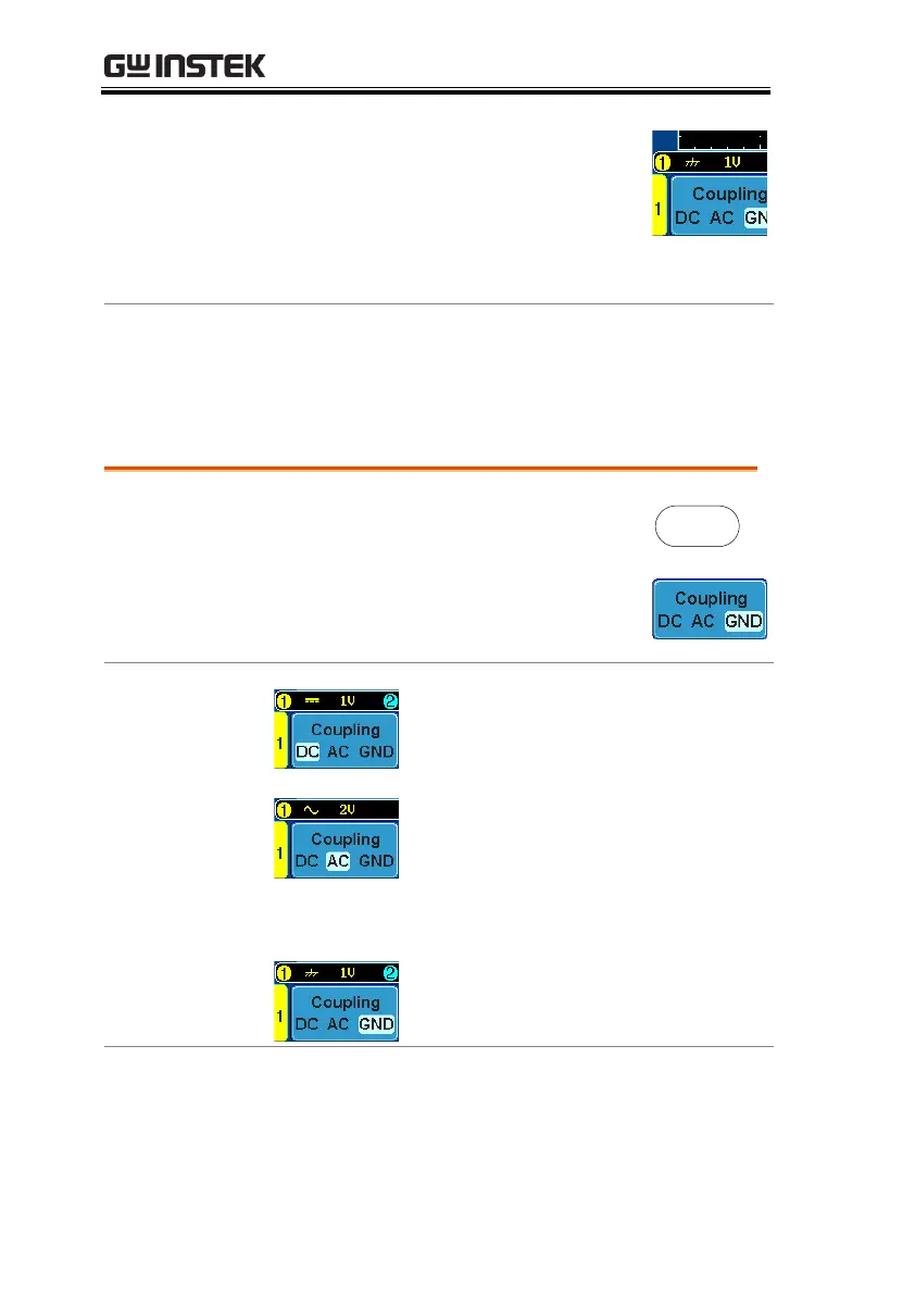
Select Coupling Mode
2. Press Coupling repeatedly to toggle
the coupling mode for the chosen
channel.
DC coupling mode. The whole
portion (AC and DC) of the signal
appears on the display.
AC coupling mode. Only the AC
portion of the signal appears on the
display. This mode is useful for
observing AC waveforms mixed with
DC signals.
Ground coupling mode. The display
shows only the zero voltage level as a
horizontal line.
Observing the AC portion of the waveform using AC
coupling

 Loading...