GDS-2000A Series User Manual
144
Trigger
The trigger configures the conditions for when the GDS-2000A
captures a waveform.
The following trigger overview only applies to the analog channels,
for triggering details using the optional logic analyzer module,
please see the GDS-2000A Options User Manual for details.
Trigger Type Overview
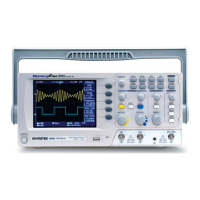
The edge trigger is the simplest trigger type. An
edge trigger triggers when the signal crosses an
amplitude threshold with either a positive or
negative slope.
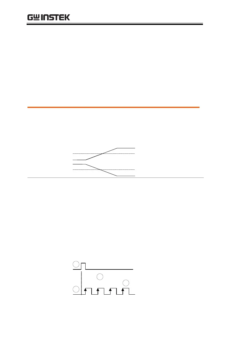
The Delay trigger works in tandem with the edge
trigger, by waiting for a specified time (duration)
or number of events before the edge trigger starts.
This method allows pinpointing a location in a
long series of trigger events.
Note: when using the delay trigger, the edge trigger
source can be any one of the channel inputs, the EXT
input or the AC line.
Delay trigger example (by event)
Ext. trigger input
(Delay trigger)

 Loading...