GDS-2000A Series User Manual
26
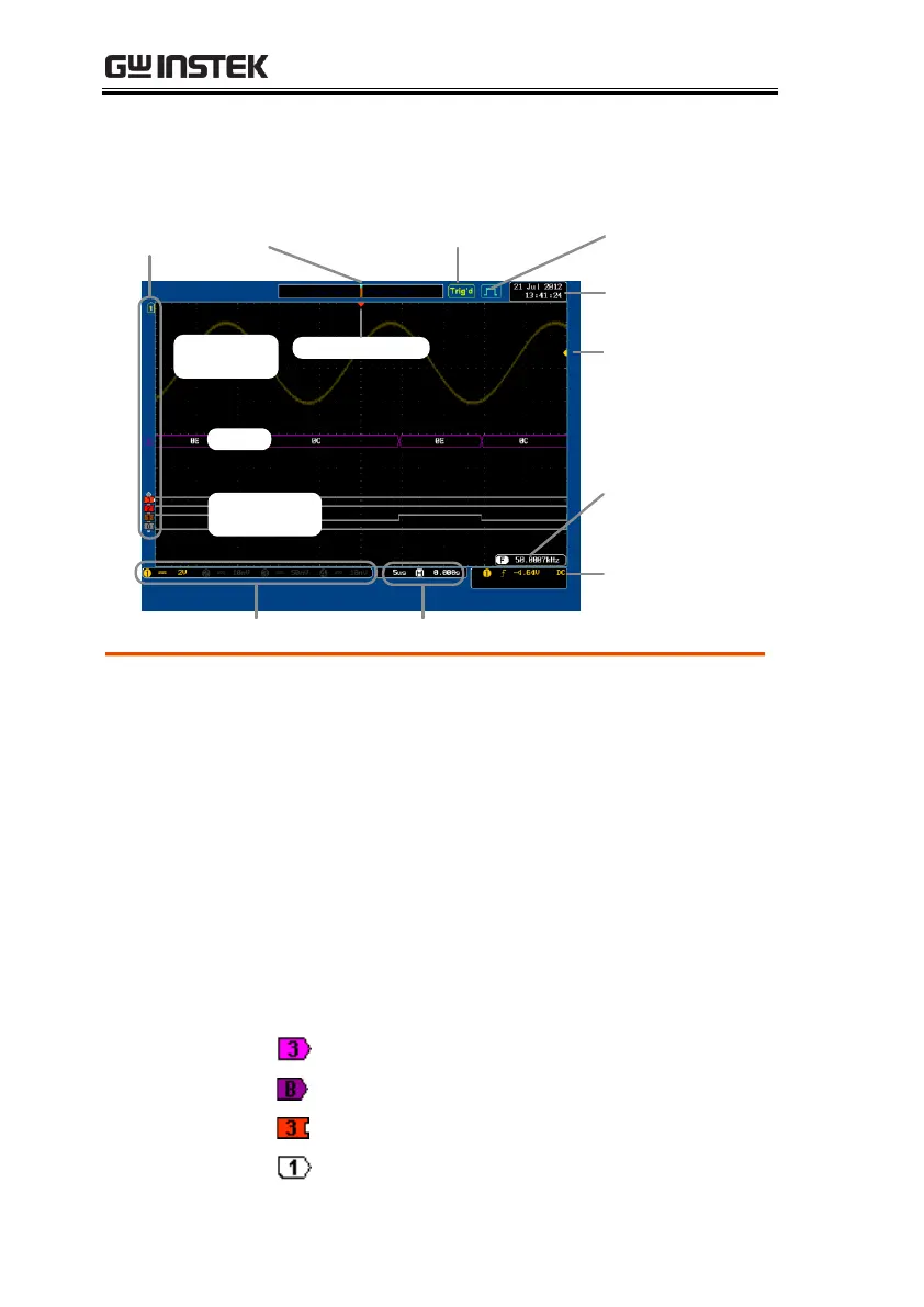
Display
Memory bar
Digital
waveforms
Analog
Waveforms
Bus
Channel status Horizontal status
Trigger
configuration
Waveform
frequency
Date and time
Trigger position
Acquisition modeTrigger Status
Trigger level
Channel
Indicators
Shows the analog input signal waveforms.
Shows the bus waveforms for either parallel or
serial buses. The values are displayed in hex or
binary.
Shows the digital channel waveforms. There can
be up to 16 digital channels.
The channel indicators show the zero volt level of
the signal waveform for each activated channel.
Any active channel is shown with a solid color.
Digital channel indicator
Reference waveform indicator

 Loading...