EasyManuals Logo

GW Instek GDS-2000A Series User Manual

GW Instek GDS-2000A Series
261 pages
To Next Page IconTo Next Page
To Previous Page IconTo Previous Page
Page #23 background imageLoading...
Page #23 background image
GETTING STARTED
23
Demo and Probe
Compensation
Outputs
Demo
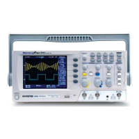
The Demo outputs are
multifunction outputs that can be
configured for probe
compensation, as a trigger output
or as a basic waveform generator
for demonstration purposes. (FM
signal, UART, I
2
C, SPI).
By default, the 3 Demo outputs are
configured as:
1: Trigger output
2: FM waveform
3: Probe Compensation signal
CAL (Demo 3) outputs a 2Vp-p,
square wave signal for probe
compensation.
Please see page 171 for details.
Logic Analyzer
Port
Logic Analyzer
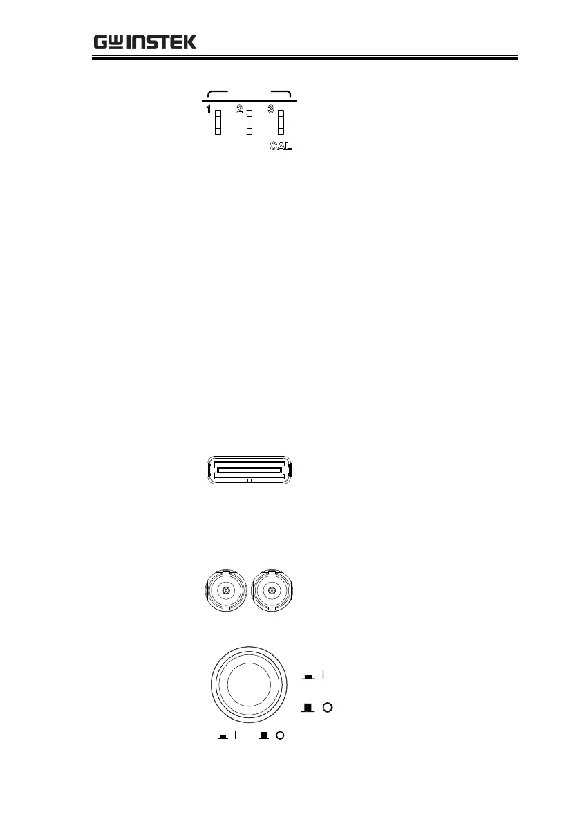
The Logic Analyzer port is used to
connect to a Logic Analyzer probe.
This port only functions if the
optional logic analyzer module is
installed.
Function
Generator Output
GEN 1
GEN 2
The function generator outputs are
used with an optional function
generator module.
Power Switch
POWER
Used to turn the power on/off.
: ON
: OFF

Table of Contents

Questions and Answers:

Question and Answer IconNeed help?

Do you have a question about the GW Instek GDS-2000A Series and is the answer not in the manual?

GW Instek GDS-2000A Series Specifications

General IconGeneral
BrandGW Instek
ModelGDS-2000A Series
CategoryTest Equipment
LanguageEnglish

Related product manuals