Quick Start
H3C S5500-EI Series Ethernet Switches
Chapter 4 Lightning Pro
tection of the Switch
4-2
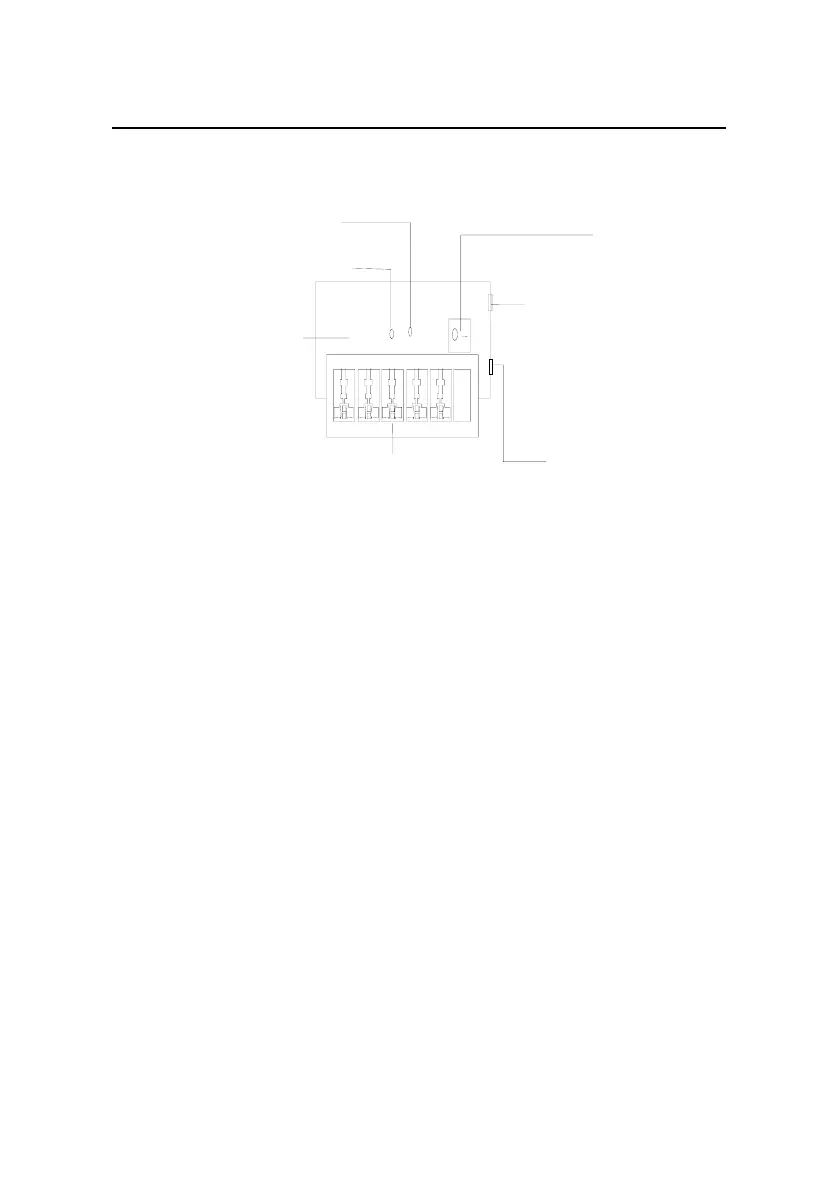
Mainboard
Grounding and polarity indicator (red) :
On means that the lines are wrongly connected
(either the ground wire is not well connected, or the live and zero lines are wrongly connected).
Please check the power supply circuit.
Power switch
Normal operation indicator (green):
On means that the arrester works normally. Otherwise, it
means that the protection circuit has been damaged.
Multipurpose power socket, connected to the device
protected by the arrester
Power socket (complied with IEC standard),
connected to the power supply of the equipment room
through power cord
Overload auto protector,
which can be manually reset.
Figure 4-1 Diagram of lightning arrester
 Loading...


