Set the vertical system
EN
Tablet1000 User manual Copyright © Qingdao Hantek Electronics Co., LTD
28
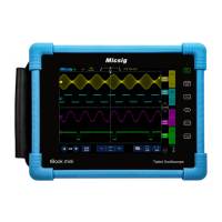
next to the value box as shown in the figure below.
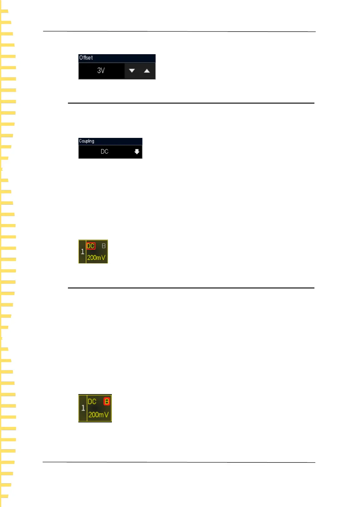
6.4 Channel coupling
Set the coupling mode to filter out unwanted signals. Open Vertical channel > Coupling
to select the coupling mode as shown in the figure below.
⚫ When the coupling mode is "DC", both DC and AC components of the measured
signal can pass through.
⚫ When the coupling mode is "AC", the DC component of the measured signal is
blocked.
⚫ When the coupling mode is "Grounded", the DC and AC components of the
measured signal are blocked.
After the coupling mode is set, the current coupling mode is displayed in the channel
label, as shown in the figure below.
6.5 20M bandwidth limit
This oscilloscope supports bandwidth limit. Setting bandwidth limit can reduce noise in
the display waveform. For example, the signal being measured is a pulse signal with high
frequency oscillations.
⚫ When the bandwidth limit is turned off, the high frequency component of the
measured signal can pass through.
⚫ If the bandwidth limit is turned on and restricted to 20 MHz, the high frequency
components larger than 20 MHz in the measured signal are attenuated.
Open Vertical channel > BW limit and select a bandwidth limit. The default state of
bandwidth limit is off. After it is enabled, the color of B on the channel label is the same
as that of the channel as shown in the figure below.
 Loading...