Acquisition
EN
Tablet1000 User manual Copyright © Qingdao Hantek Electronics Co., LTD
54
When the average acquisition mode is selected, the average number can be set. The
higher the average number is, the lower the noise is. The range is 2-256.
11.3 Display mode
The display mode can be YT, XY, and scroll.
YT mode:
The most commonly used display mode, Y-axis represents the voltage, X-axis
represents the time. When the horizontal time base is greater than 100ms, the
oscilloscope automatically enters the scanning mode.
When the large time base is large (such as 200ms and above), sometimes the waveform
will not be displayed for a long time. This is because under YT mode, waveform must be
triggered before display. This time has a great relationship with the time base, which can
be roughly calculated as: the number of grids on the left of the trigger position * the time
base gear. If you want to reduce the wait time, you can move the trigger position to the
left. We do not consider moving the trigger position off the waveform screen.
XY mode:
The oscilloscope converts two data channels from a voltage-time display to a
voltage-voltage display.
XY mode is used to analyze the phase difference, such as those described by lissajous
figures.
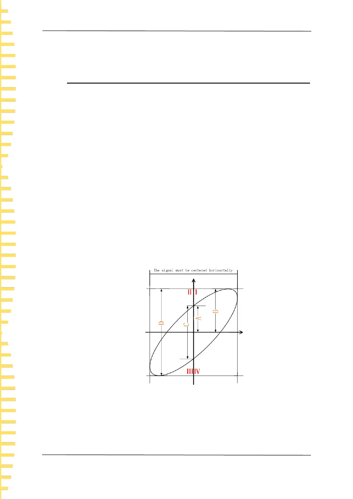
Figure 11.1 Phase difference schematic diagram
According to sinθ=A/B or C/D, where θ is the angle difference between channels, A, B,
C and D are defined in the figure above. Thus the angle difference can be obtained,
namely: θ=±arcsin(A/B) or ±arcsin(C/D).
If the principal axis of the ellipse is in quadrants I and III, the obtained phase difference
angle should be in quadrants I and IV, that is, in (0 to π/2) or (3π/2 to 2π). If the
 Loading...