PAGE 2.2 - 40 OPERATION MARK IV HD J2 TAMPER
REVISED 10 -2020 JUPITER II BULLETIN 5082505
2.2
2.2.10 Machine Status Panel - See Figures 2.2-24 and 2.2-25
(6) Engine RPM Indicator: The slider will highlight yellow to display the actual engine
RPM increases or decreases.
(7) Work Rate Indicator: The work rate indicator shows the time elapsed for the current
work mode (elapsed time varies with the mode; i.e., work, travel, repairs, trains, etc.),
the speed of working in ties per minute indicated by the highlighted blue slider and
the maximum work speed achieved in the current work period indicated by the black
arrow to the left of the slider.
(8) Vibrators On Indicators / Double Tamp Timer: When the applicable
Workhead Vibrator Keys on the Left Operator Keypad are pressed to turn
ON the vibrator motors, the applicable left and/or right indicator will highlight
yellow. When the applicable Workhead Vibrator Keys are pressed again to
turn OFF the vibrator motors, the applicable left and/or right indicator will highlight
gray.
a. The values shown on the side of each vibrator indicator indicators the current
setting of how many tamping cycles the workheads will do.
b. The lower value shown indicates the current setting of the double tamp timer.
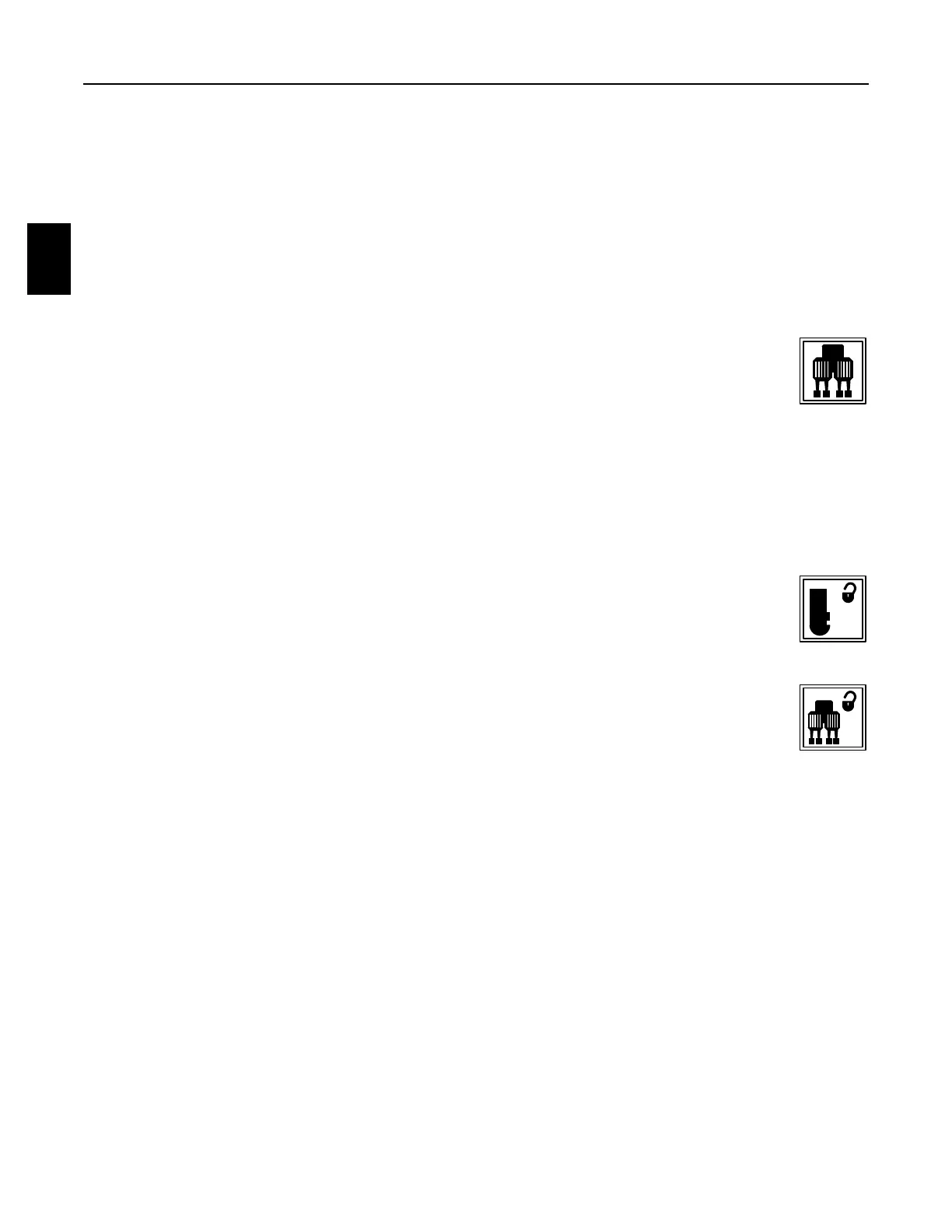
(9) Combo Clamp Lock Indicator: When the Combo Clamp Key on the Left
Operator Keypad is pressed to UNLOCK the Combo Clamps, the indicator
will highlight yellow. When the Combo Clamp Lock Key is pressed again to
LOCK the Combo Clamps, the indicator will highlight gray.
(10) Workhead Lock Indicator: When the Workhead Lock Key on the Left
Operator Keypad is pressed to UNLOCK the Workheads, the indicator will
highlight yellow. When the Workhead Lock Key is pressed again to LOCK
the Workheads, the indicator will highlight gray.
(11) Buggy Selection Indicator: The value shown indicates the current setting of how
many buggy pusher sections are being used.
 Loading...