PAGE 2.1 - 8 OPERATION MARK IV HD J2 TAMPER
REVISED 10 - 2020 CONTROLS BULLETIN 5082505
2.1
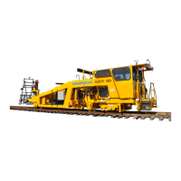
2.1.1 Controls / Locks Locations
Controls Locations - See Figures 2.1-2 and 2.1-3
The MARK IV HD J2 Tamper has the following controls and components located in the general
areas illustrated on the machine:
(1) Engine
(2) Air Cleaner
(3) Pump Drive / Hydraulic Pumps
(4) Cab
(5) Cab Air Conditioner / Pressurizer Unit - Right
(6) Strobe Light - Rear
(7) Air Horns
(8) Combo Rail Clamps - Left / Right
(9) Tamping Workheads - Left / Right
(10) Hydraulic Reservoir / Filters
(11) Hydraulic Fill Pump, Switch, Hose and Filters
(12) Hydraulic Oil Cooler
(13) Fuel Tank / Fill Spout
(14) Wheels / Axles / Brakes / Suspension - Front / Rear
(15) Main Batteries / Master Disconnect Switch Compartment - Left
(16) Diesel Emissions Fuel Tank - Right
(17) Storage Compartment - Left / Right
(18) Emergency Pump Switch / Emergency Pump - Right
(19) Remote Emergency Stop / Air Horn Switches Option - Left / Right
(20) Air Dryer / Purge Tank
(21) Air System Reservoir / Drain Cable
(22) Ladders & Walkways - Left / Right
(23) Shadowboard Lock / Lift Valves - Right
(24) Shadowboard - Left / Right
(25) Liner Flags - Left / Right
(26) Liner Light Shields - Left / Right
(27) Liner Receivers Lock / Lift Valves - Right
(28) Liner Receivers - Left / Right
(29) Surfacing Receivers - Left / Right
(30) Lifting Points
(31) Power Distribution Box (PDB) - Left
(32) Distance Encoder - Right
(33) Projector Buggy Lift / Control Valve - Right
(34) Projector Buggy
(35) Pusher / Recorder Buggies
(36) Lining Projectors - Left / Right
(37) Surfacing Projectors - Left / Right
(38) Tie Finder Dual Probes / Sensor Box - Left / Right
(39) Serial Number Tag
(40) Video Camera Option
(41) Laser Alignment Cart Option
 Loading...