Bus configuration
16 A01185_11_X00_00 HBM: public CANHEAD
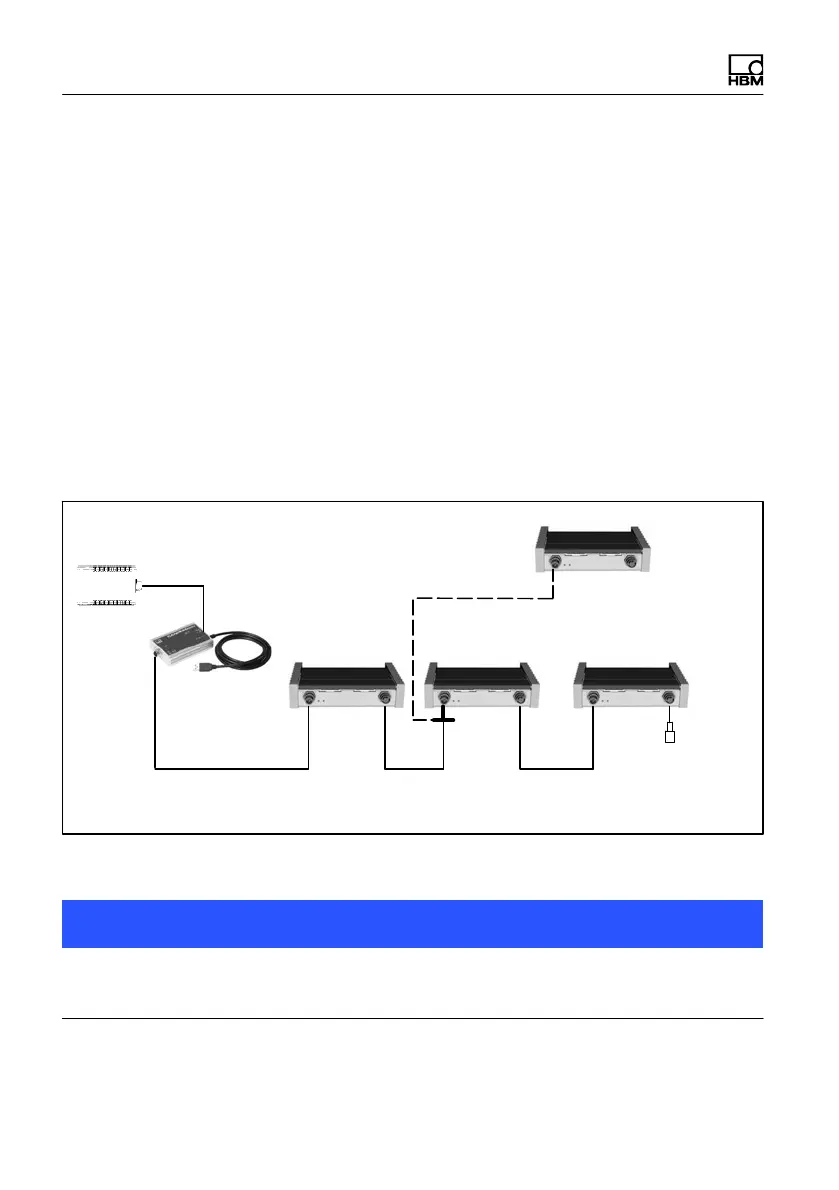
5.2 Bus configuration with CANHEADdirect
CANHEADdirect includes a hardware interface and an API (Application Pro
gramming Interface). The CANHEADdirect module enables CANHEAD mod
ules to be directly connected to a PC (USB port).
A power supply unit provides the voltage (10...30 V) for the CANHEADdirect
module. A CAN bus is used for data transmission between the CANHEAD
modules and the CANHEADdirect (see chapter 9).
The PC-internal API uses CANopen protocol for communication with the CAN
HEAD modules. CANHEADdirect enables the CAN bus voltage supply to be
switched on and off to reset the bus.
An example program can be used to check the system functions and parame
terize the sensors using HBM's catman software.
Termination
resistor
CAN bus linear bus structure with trunk and drop lines
10
channels
10 channels
maximal 5 CANHEAD modules
T‐conn.
no termination
resistor required
10
channels
10
channels
NTX001
CANHEADdirect
Fig. 5.2 Connection to CANHEADdirect
Notice
It is preferable to install CAN bus as a line bus. Only use the T‐connector on
the input side.