Bus configuration
CANHEAD A01185_11_X00_00 HBM: public 15
5 Bus configuration
With a bus system, intelligent measurement electronics are interconnected or
connected to the central evaluator and server / PC by a data line.
A CAN bus with a fixed baud rate has been chosen for the transfer of data
generated in the base module and in the amplifier module. This gives the opti
mum ratio between management data, parameterization data and process data
(measured values) with at the same time faster data transfer rates and greater
bus lengths.
The bus allows cyclic and acyclic data to be transferred. This ensures that the
synchronized AD converter operating in parallel can process in real time. A
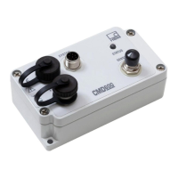
HBM specific CAN protocol is used for data transport of up to 12 CANHEADs
in one bus line.
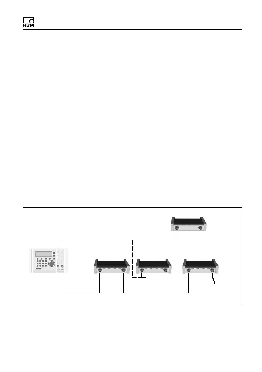
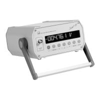
5.1 Bus configuration with MGCplus
The master here is the ML74B communications module, to read the data into
an MGCplus system. In conjunction with catman measurement software, this
provides a tried and tested plug‐and‐play solution.
MGCplus
ML74B / AP74
1)
Termination
resistor
CAN bus linear structure with trunk and drop lines
10
channels
10 channels
max. 12 CANHEAD modules
T‐conn.
no termination
resistor required
10
channels
10
channels
1)
The AP74 connection board in the MGCplus provides an built‐in termination resistor.
Fig. 5.1 Connection to MGCplus
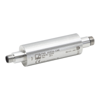
The T‐connector 1‐CANHEAD‐M12‐T is used if a drop line is to be established.