162 Fixed Cycles: Pocket Milling / Stud Milling / Slot Milling
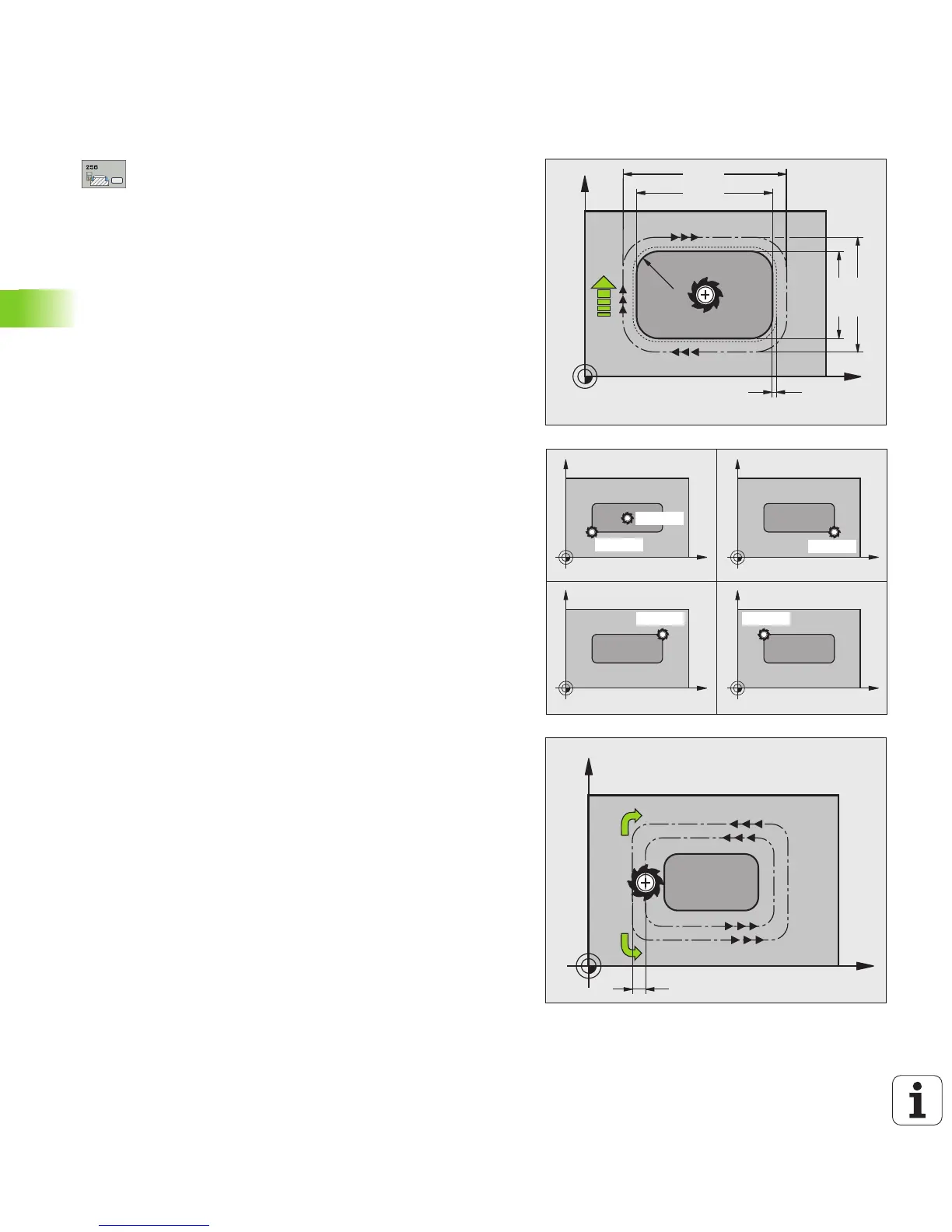
5.6 RECTANGULAR STUD (Cycle 256, DIN/ISO: G256)
Cycle parameters
U First side length Q218: Stud length, parallel to the
reference axis of the working plane. Input range 0 to
99999.9999
U Workpiece blank side length 1 Q424: Length of the
stud blank, parallel to the reference axis of the
working plane. Enter Workpiece blank side length 1
greater than First side length. The TNC performs
multiple stepovers if the difference between blank
dimension 1 and finished dimension 1 is greater than
the permitted stepover (tool radius multiplied by path
overlap Q370). The TNC always calculates a constant
stepover. Input range 0 to 99999.9999
U Second side length Q219: Stud length, parallel to the
minor axis of the working plane. Enter Workpiece
blank side length 2 greater than Second side
length. The TNC performs multiple stepovers if the
difference between blank dimension 2 and finished
dimension 2 is greater than the permitted stepover
(tool radius multiplied by path overlap Q370). The TNC
always calculates a constant stepover. Input range 0
to 99999.9999
U Workpiece blank side length 2 Q425: Length of the
stud blank, parallel to the minor axis of the working
plane. Input range 0 to 99999.9999
U Corner radius Q220: Radius of the stud corner. Input
range 0 to 99999.9999
U Finishing allowance for side Q368 (incremental):
Finishing allowance in the working plane, is left over
after machining. Input range 0 to 99999.9999
U Angle of rotation Q224 (absolute): Angle by which
the entire stud is rotated. The center of rotation is the
position at which the tool is located when the cycle is
called. Input range -360.000 to 360.000
U Stud position Q367: Position of the stud in reference
to the position of the tool when the cycle is called:
0: Tool position = Center of stud
1: Tool position = Lower left corner
2: Tool position = Lower right corner
3: Tool position = Upper right corner
4: Tool position = Upper left corner