462 Touch Probe Cycles: Automatic Kinematics Measurement
18.1 Kinematic Measurement with TS Touch Probes (Option KinematicsOpt)
18.1 Kinematic Measurement with
TS Touch Probes (Option
KinematicsOpt)
Fundamentals
Accuracy requirements are becoming increasingly stringent,
particularly in the area of 5-axis machining. Complex parts need to be
manufactured with precision and reproducible accuracy even over
long periods.
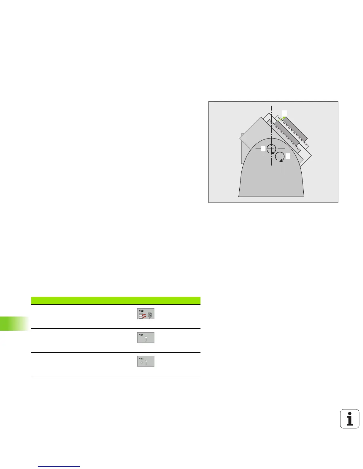
Some of the reasons for inaccuracy in multi-axis machining are
deviations between the kinematic model saved in the control (see
figure 1 at right), and the kinematic conditions actually existing on the
machine (see figure 2 at right). When the rotary axes are positioned,
these deviations cause inaccuracy of the workpiece (see figure 3 at
right). It is therefore necessary for the model to approach reality as
closely as possible.
The new TNC function KinematicsOpt is an important component
that helps you to really fulfill these complex requirements: A 3-D touch
probe cycle measures the rotary axes on your machine fully
automatically, regardless of whether they are in the form of tables or
spindle heads. A calibration sphere is fixed at any position on the
machine table, and measured with a resolution that you define. During
cycle definition you simply define for each rotary axis the area that you
want to measure.
From the measured values, the TNC calculates the static tilting
accuracy. The software minimizes the positioning error arising from
the tilting movements and, at the end of the measurement process,
automatically saves the machine geometry in the respective machine
constants of the kinematic table.
Overview
The TNC offers cycles that enable you to automatically save, check
and optimize the machine kinematics: