HEIDENHAIN iTNC 530 191
7.4 CONTOUR DATA (Cycle 20, DIN/ISO: G120)
Cycle parameters
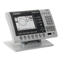
U Milling depth Q1 (incremental): Distance between
workpiece surface and bottom of pocket. Input range
-99999.9999 to 99999.9999
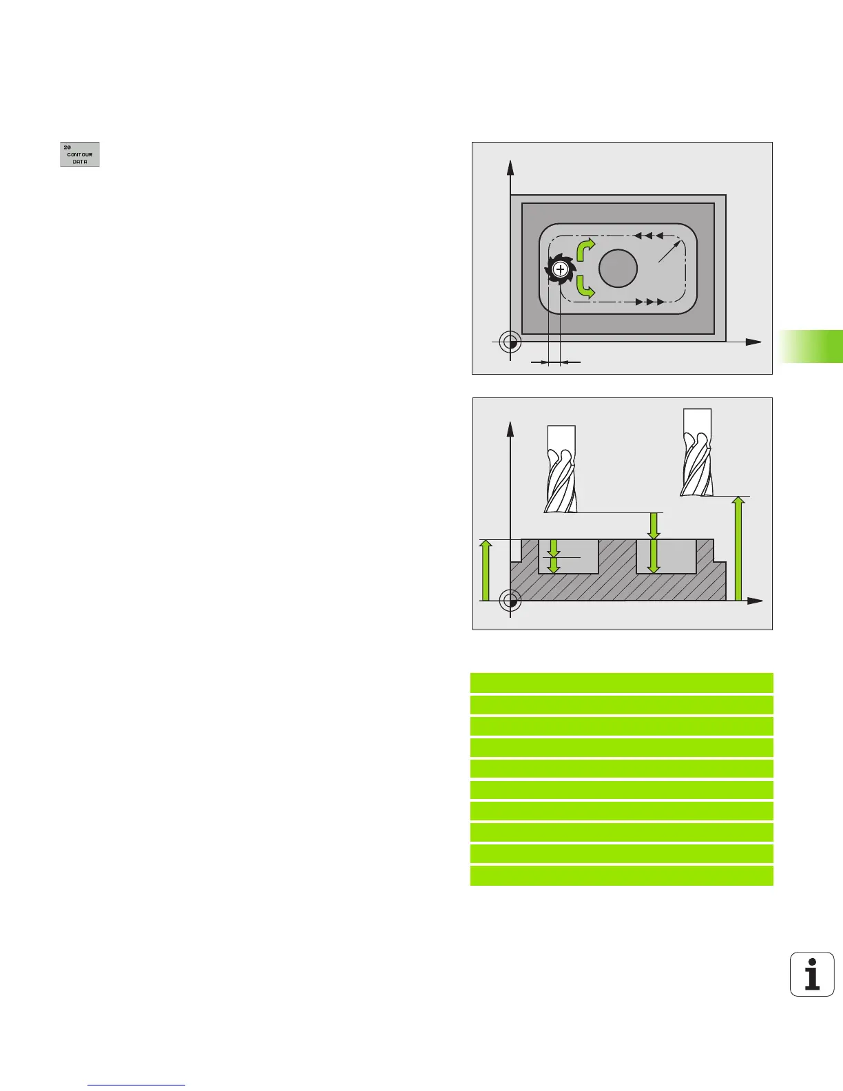
U Path overlap factor Q2: Q2 x tool radius = stepover
factor k. Input range -0.0001 to 1.9999.
U Finishing allowance for side Q3 (incremental):
Finishing allowance in the working plane. Input range:
-99999.9999 to 99999.9999
U Finishing allowance for floor Q4
(incremental): Finishing allowance in the tool axis.
Input range -99999.9999 to 99999.9999
U Workpiece surface coordinate Q5 (absolute):
Absolute coordinate of the workpiece surface. Input
range -99999.9999 to 99999.9999
U Setup clearance Q6 (incremental): Distance between
tool tip and workpiece surface. Input range 0 to
99999.9999, alternatively PREDEF
U Clearance height Q7 (absolute): Absolute height at
which the tool cannot collide with the workpiece (for
intermediate positioning and retraction at the end of
the cycle). Input range -99999.9999 to 99999.9999,
alternatively PREDEF
U Inside corner radius Q8: Inside “corner” rounding
radius; entered value is referenced to the path of the
tool center. Q8 is not a radius that is inserted as a
separate contour element between programmed
elements! Input range 0 to 99999.9999
U Direction of rotation? Q9: Machining direction for
pockets.
Q9 = –1 up-cut milling for pocket and island
Q9 = +1 climb milling for pocket and island
Alternative: PREDEF
You can check the machining parameters during a program
interruption and overwrite them if required.
Example: NC blocks
57 CYCL DEF 20 CONTOUR DATA
Q1=-20 ;MILLING DEPTH
Q2=1 ;TOOL PATH OVERLAP
Q3=+0.2 ;ALLOWANCE FOR SIDE
Q4=+0.1 ;ALLOWANCE FOR FLOOR
Q5=+30 ;SURFACE COORDINATE
Q6=2 ;SETUP CLEARANCE
Q7=+80 ;CLEARANCE HEIGHT
Q8=0.5 ;ROUNDING RADIUS
Q9=+1 ;DIRECTION