EN – Translation of the original user manual - 2.0 | 2019
5.2 FULL VIEW OF THE CONTROL SYSTEM
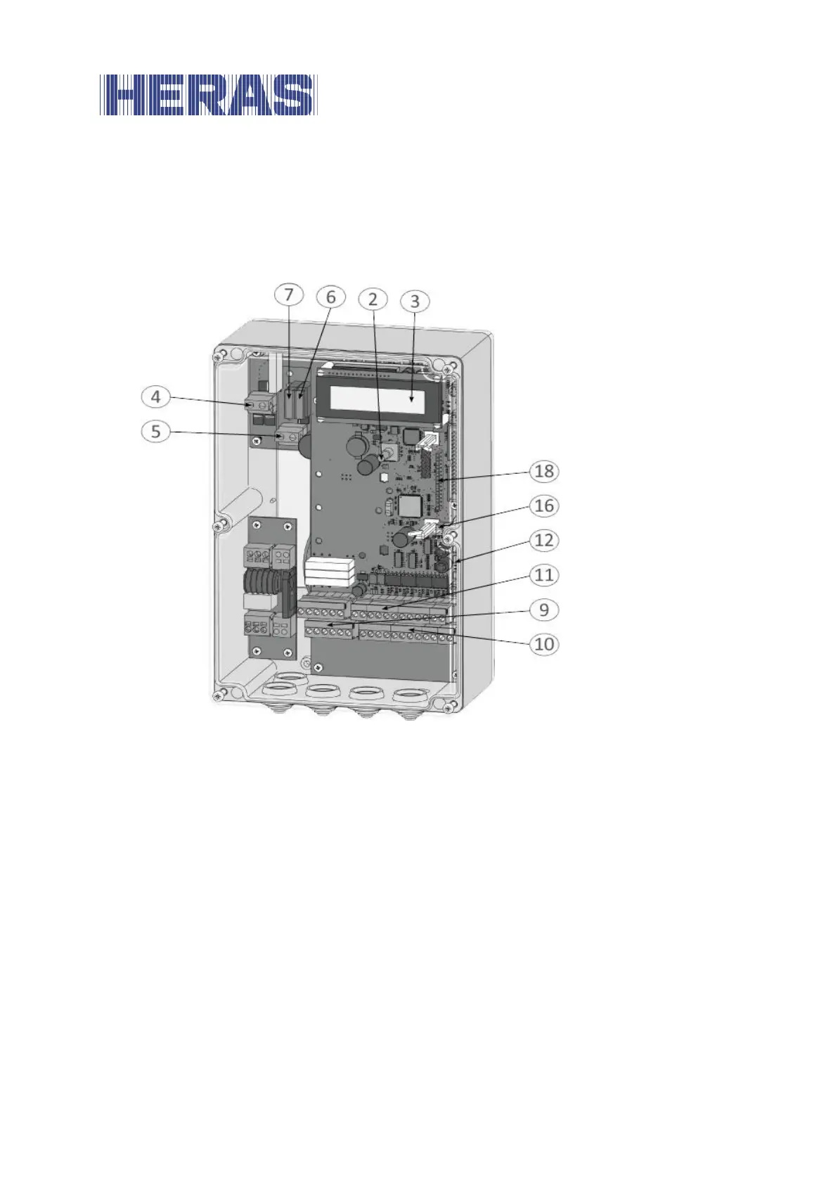
The drawing showing a full view of the control system provides an overview of all
its relevant parts referred to in the text of these operating instructions.
Illustration 7: view of control unit
Designations of the figure numbers:
2 Rotary switches and pushbuttons for display selection and settings
3 2-line LC text display
4 Motor connection
5 Power supply connection (20 – 35 V
DC
)
6 Fuse F2 for the control electronics (1 A/black)
7 Fuse F1 for the power electronics and the motor (10 A/red)
9 Connections for the relay outputs Rel1 to Rel3
10 Connections for the supply of the external 24 V
DC
devices and control
elements as well as for the fixed safety contact strips
11 Connections for the inputs of the command devices, light barrier and ISK
coil core
12 Electrical evaluation unit for the accompanying safety contact strips:
INDUS onboard 70-757 board