EN – Translation of the original user manual - 2.0 | 2019
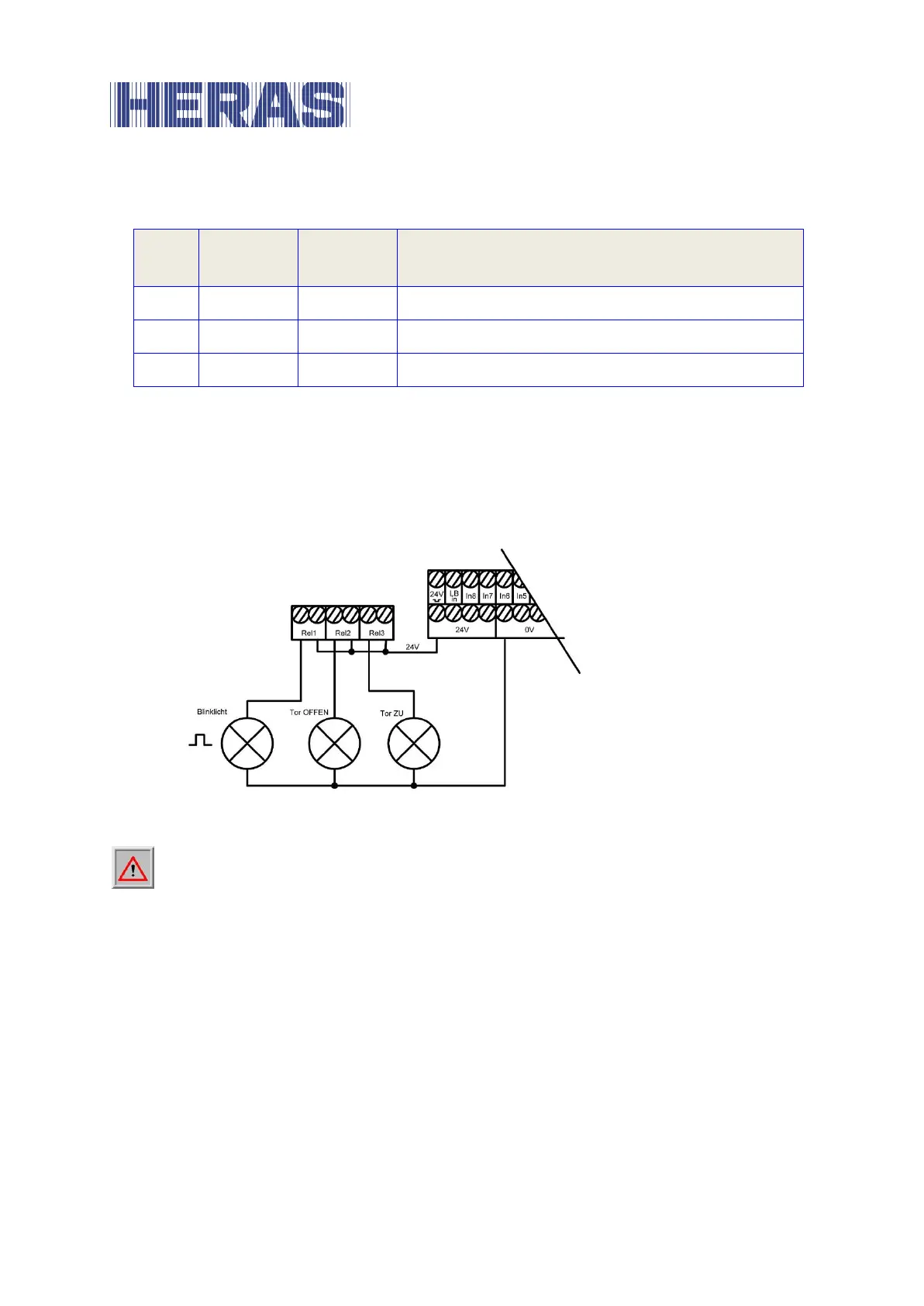
The relays are preallocated with the following functions:
Flashlight or rotating beacon
Gate CLOSED status display
The output of Rel1 with warning light function is permanently switched on during
every gate movement and at the start of the pre-warning period. The flashing
function must be effected by the connected lamp.
Indicator lamps with a supply voltage of 24 V can be connected as shown in the
figure below.
Illustration 12: Connection of relay to 24 V
DC
Attention: When connecting external loads to the 24 V power supply from
the control system, the maximum current carrying capacity of 500 mA must
be observed. In addition, the maximum load of 250 W must be observed for each
individual relay.
6.7 RADIO RECEIVER AND ARIAL
Optionally, the control system can be equipped with a radio receiver for handheld
transmitters for the remote control of the gate. The radio receiver of the HMD24
operates at 868 MHz with FM modulation. The radio receiver is plugged into the
female connector strip to the right of the slot for the communication interface.
An external aerial can be connected to this receiver underneath the module using
the plug-in terminal.