EN – Translation of the original user manual - 2.0 | 2019
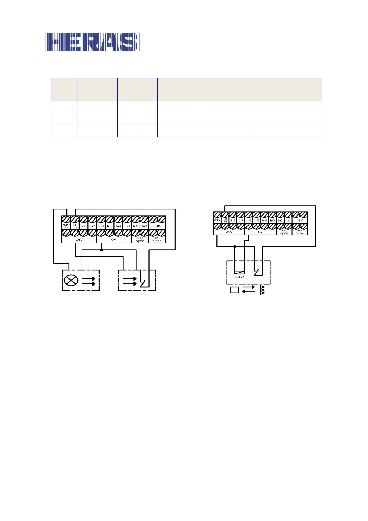
Output test signal (e.g. for light barrier)
Input signal from the light barrier
The upper left-hand terminal no. 1 with the designation “24V ¯|_|¯” is a 24-volt
supply, which is briefly switched off at periodic intervals for test purposes. The
transmitter of a light barrier, for example, can be connected to this power supply.
The function of the light barrier input signal is checked during the brief switch-off
phase.
Illustration 9: Connection of tested one-way light barrier
Illustration 10: Connection of reflex light barrier
The two representations show, as examples, the different connections of a one-
way light barrier tested by blocking the transmitter and an untested reflex light
barrier.
Connecting a light barrier
6.5.5
A one-way light barrier, as connected in the installation overview in Section 6.5.6,
is installed and parameterised in the following way:
De-energize the control system.
Fit the transmitter and receiver of the light barrier in a mechanically sound
manner.
Connect both modules to the 0 V of the electrical power supply and 24 V
from the control system.
Connect the signal line from the receiver module to the ‘LB in’ terminal.