EN – Translation of the original user manual - 2.0 | 2019
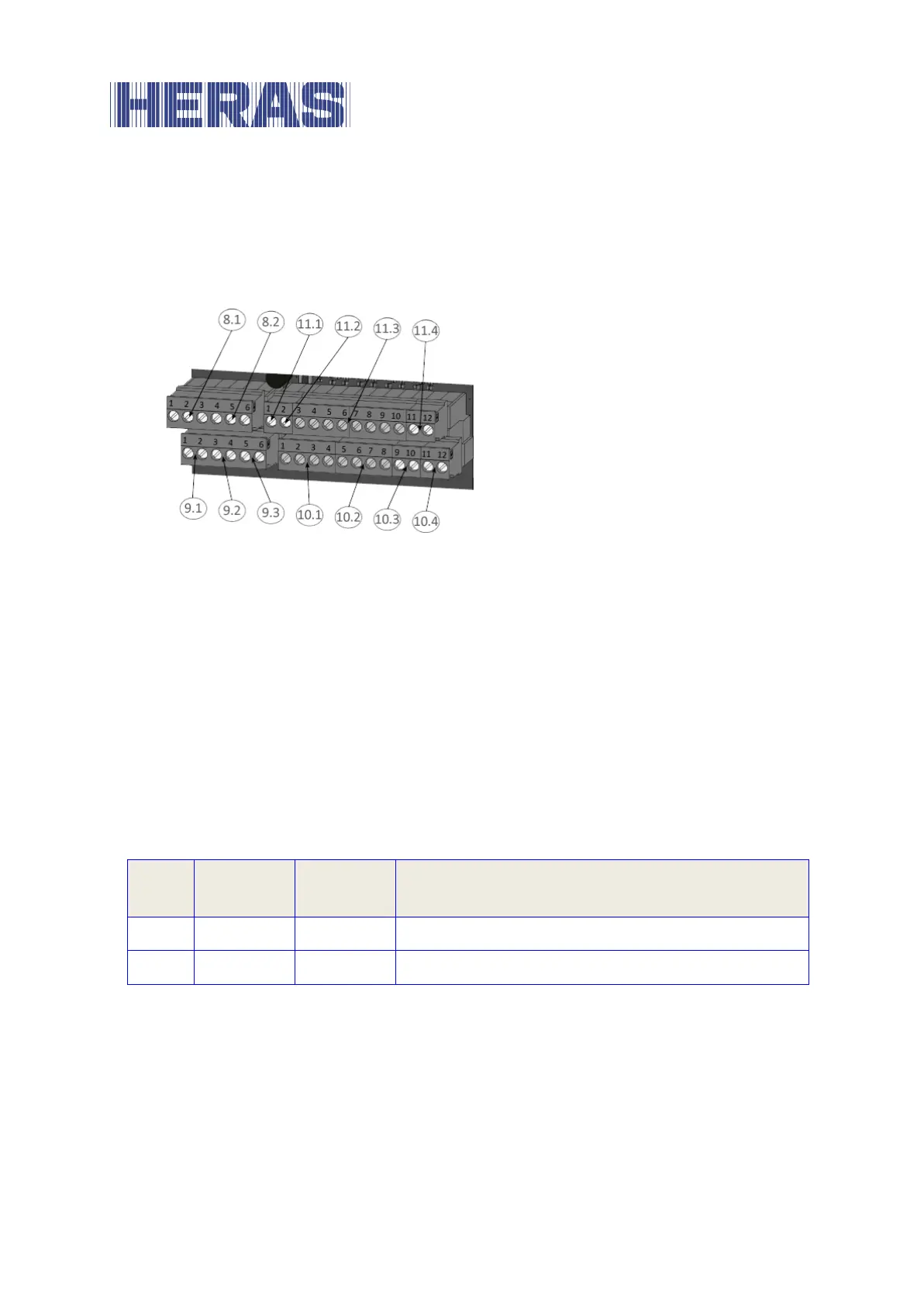
right-hand block is for command devices and sensors. The terminal designation is
printed onto the board just below the terminals.
For better identification, these terminals are shown in the figure below with
further details.
Illustration 8: Connection of external devices
Supply of external devices with 24 V
DC
6.3.1
The control system features an isolated and voltage-stabilized 24 V
DC
power
supply able to supply a maximum current of 500 mA for the supply of the external
devices, command devices and sensors. This supply voltage is fused on the
printed circuit board by an automatically resetting fuse.
The 24 volts are available on the bottom terminal strip at the left-hand terminals
numbered 1 to 4 with the designation “+24V”.
Adjacent to this, on the right-hand side, is the associated ground potential at the
terminals numbered 5 to 8 with the designation “0V”.
+24 V direct voltage supply
Ground potential for the external 24 V loads