EN – Translation of the original user manual - 2.0 | 2019
Switch on the power supply to the control system.
Menu: “Service Access”, “Password Input”: Enter password.
Menu: “Settings”, “Safety”, set “Light barrier” to the value 1.
Exit menu
Check that the light barrier is correctly connected by the “Sensor display”
screen and check the response of the gate during gate movement in the
CLOSE direction in “automatic mode”.
In the HMD24, this is the default value in the menu.
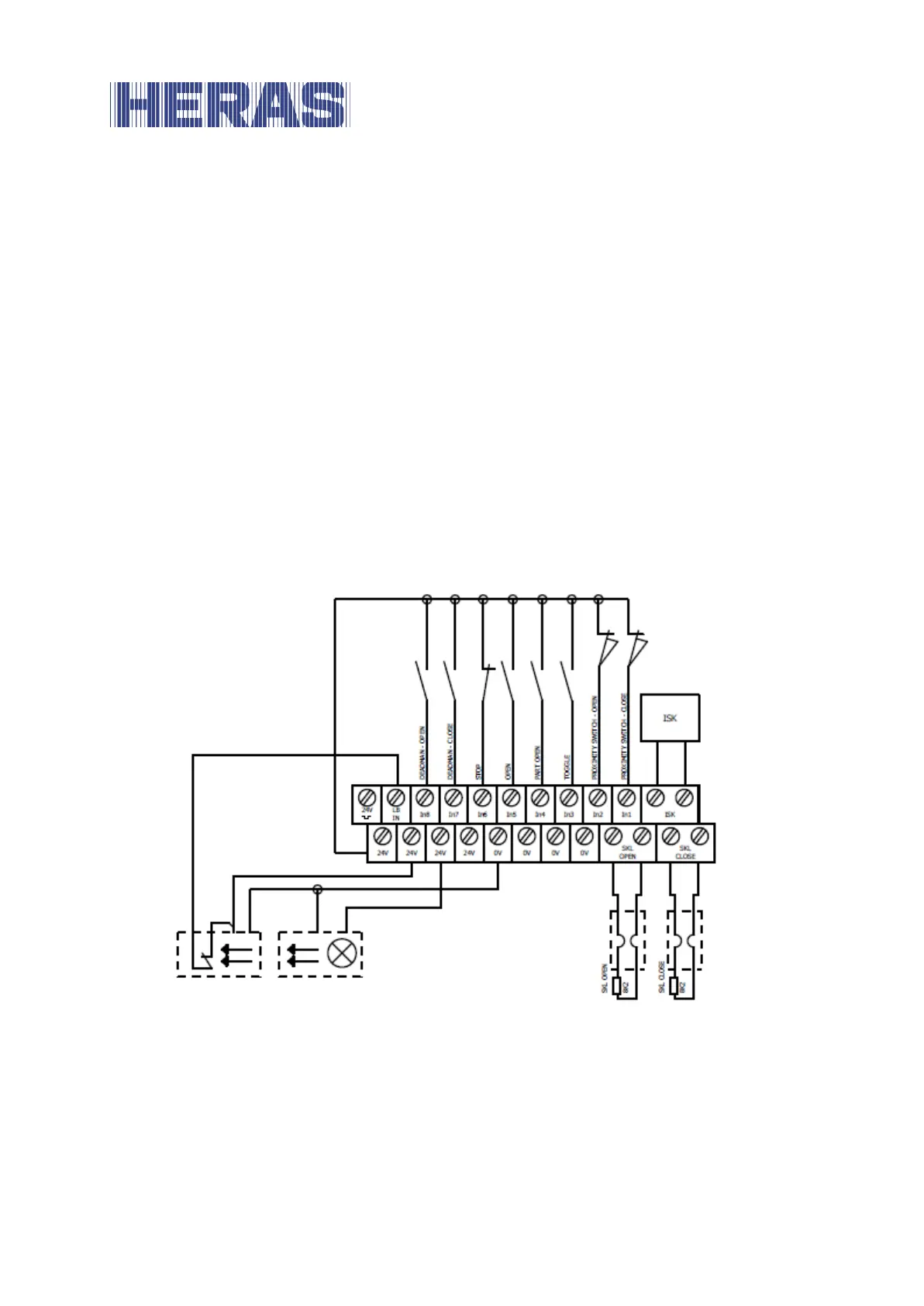
Overview installation plan of the inputs 6.5.6
The HMD24 is configured for operation with limit switches. The following drawing
shows a typical configuration for the connection of the command devices and
sensors to the inputs:
Illustration 11: Example installation with limit switches, light barrier and safety contact strips
6.6 RELAY OUTPUTS
HMD24 provides three relays with normally open contacts for signalling and
lighting purposes. The switching contacts are potential-free and can switch ohmic
loads of at most 250 W.