EN – Translation of the original user manual - 2.0 | 2019
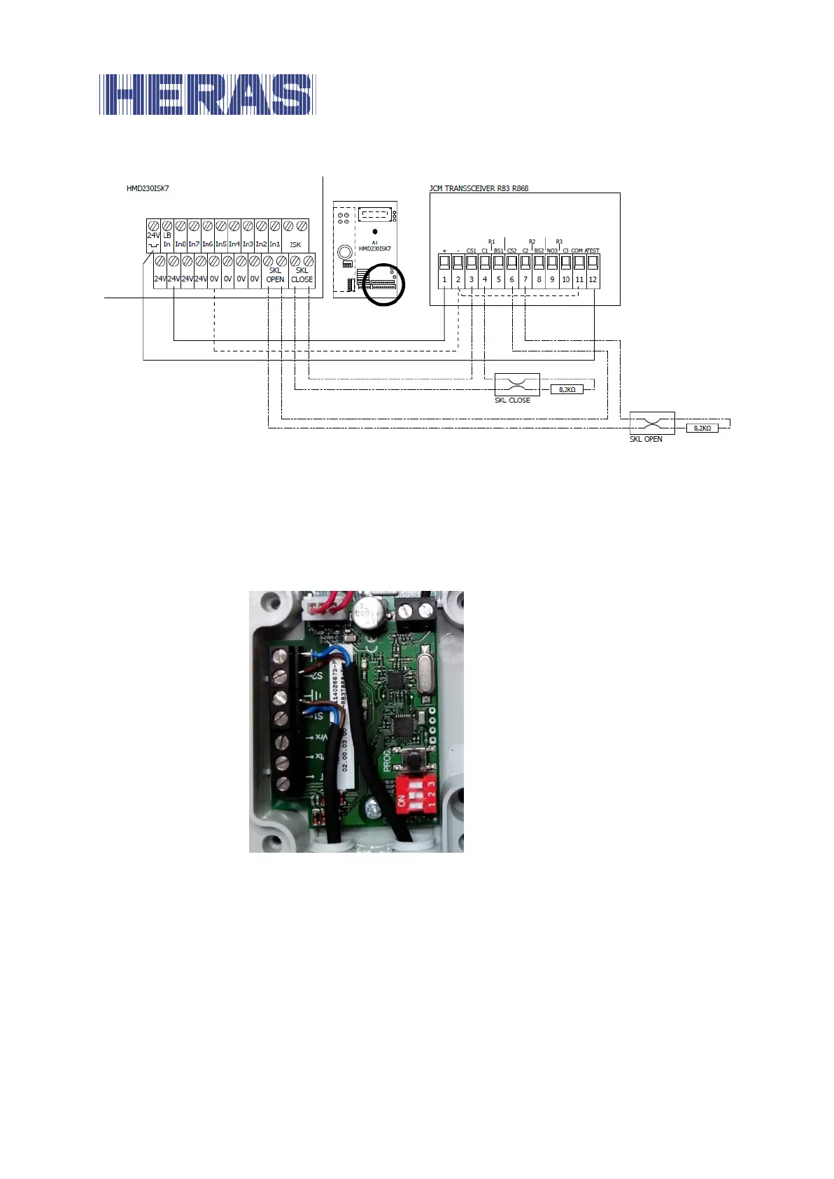
Illustration 14: Example installation with connection of JCM transceiver RB3R868 to the control system
The four DIP switches of “SW1” on the radio receiver are set to “Off, Off, Off, On”.
The two accompanying safety contact strips on the gate are connected to
terminals S1 and S2 on the associated transmitter of the JCM “RB3T868” radio
transmission system as shown in the following figure:
Illustration 15: Example connection of safety contact strips to the JCM RB3R686 transmitter
The three DIP switches of “SW1” on the radio transmitter are switched to OFF,
ON, OFF.
Following a correct hardware installation, the control system is switched on and
configured for the JCM radio system as follows:
Switch on the power supply to the control system.
Menu: “Service Access”, “Password Input”: Enter password.
Menu: “Settings”, “Safety”, ”Activate JCM”.