13.3 Measurement Specifications
170
Note 1: All CH4 displays turn ON when CH4 is set to AC+DC or DC.
Note 2: When CH4 is turned OFF, all CH4 display values and waveforms are also turned OFF.
Note 3: Meaning of "*" in the "MAX/MIN/AVG" column
Indicates that maximum, minimum, and average values (all) can be displayed during the MAX/MIN/AVG TIMEPLOT interval.
Note 4: Meaning of "**" in the "MAX/MIN/AVG" column
Indicates that maximum and minimum values (all) can be displayed, regardless of the MAX/MIN/AVG TIMEPLOT interval.
*1: CH3 is calculated but not displayed. It can be output only as binary data.
*2: Select either.
Zero-phase voltage
unbalance factor
Voltage negative-
phase unbalance factor
Uunb0, Uunb - - sum sum sum sum *
Zero-phase current
unbalance factor
Current negative-phase
unbalance factor
Iunb0, Iunb - - sum sum sum sum *
High-order harmonic
voltage component
UharmH 1,4 1,2,4 1,2,4 1,2,3,4 1,2,3,4 1,2,3,4 *
High-order harmonic
current component
IharmH 1,4 1,2,4 1,2,4 1,2,3,4 1,2,3,4 1,2,3,4 *
Harmonic voltage
(orders 0 to 50)
Uharm 1,4 1,2,4 1,2,4 1,2,3,4 1,2,3,4 1,2,3,4 *
Harmonic current
(0 to 50th)
Iharm 1,4 1,2,4 1,2,4 1,2,3,4 1,2,3,4 1,2,3,4 *
Harmonic power
(0 to 50th)
Pharm 1 1,2,sum sum sum 1,2,3,sum 1,2,3,sum *
Inter-harmonic voltage
(0.5to 49.5th)
Uiharm 1,4 1,2,4 1,2,4 1,2,3,4 1,2,3,4 1,2,3,4 *
Inter-harmonic current
(0.5 to 49.5th)
Iiharm 1,4 1,2,4 1,2,4 1,2,3,4 1,2,3,4 1,2,3,4 *
Harmonic voltage
phase angle
(1 to 50th)
Uphase 1,4 1,2,4 1,2,4 1,2,3,4 1,2,3,4 1,2,3,4
Harmonic current
phase angle
(1 to 50th)
Iphase 1,4 1,2,4 1,2,4 1,2,3,4 1,2,3,4 1,2,3,4
Harmonic voltage-cur-
rent phase difference
(1to 50th)
Pphase 1 1,2,sum sum sum 1,2,3,sum 1,2,3,sum *
Total harmonic voltage
distortion factor
Note2
Uthd-F/Uthd-R 1,4 1,2,4 1,2,4 1,2,3,4 1,2,3,4 1,2,3,4 *
Total harmonic current
distortion factor
Note2
Ithd-F/Ithd-R 1,4 1,2,4 1,2,4 1,2,3,4 1,2,3,4 1,2,3,4 *
K factor KF 1,4 1,2,4 1,2,4 1,2,3,4 1,2,3,4 1,2,3,4 *
Voltage waveform
comparison
Wave 1 1,2 1,2 1,2,3 1,2,3 1,2,3
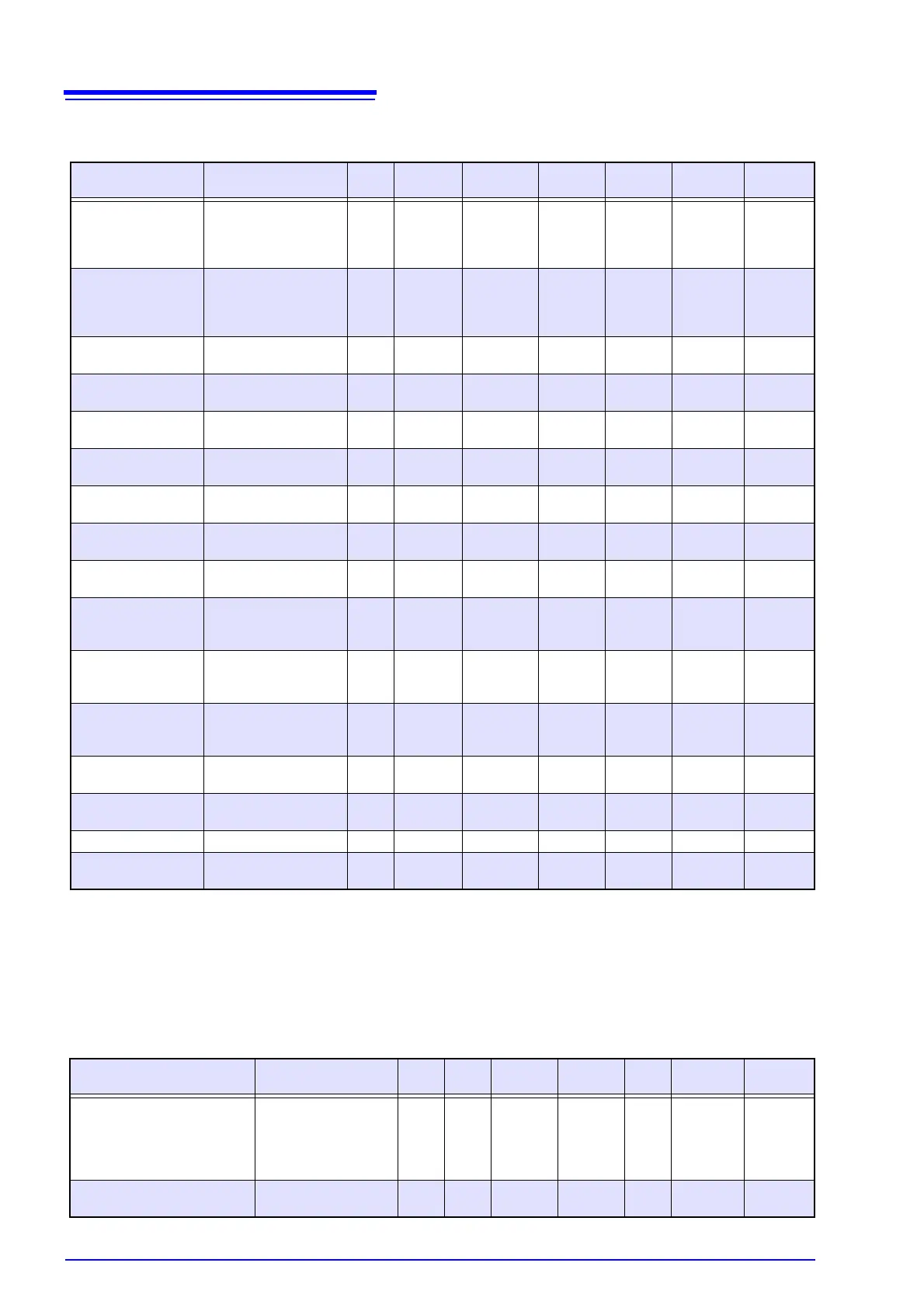
(5) Items measured without gaps and aggregated every approx. 200 ms
(about once every 10 cycles at 50 Hz, every 12 cycles at 60 Hz, or every 80 cycles at 400 Hz)
Measurement items Notation 1P2W 1P3W 3P3W2M 3P3W3M 3P4W 3P4W2.5E MAX/MIN
/AVG
(6) Flicker measurement items:
Measurement items Notation 1P2W 1P3W 3P3W2M 3P3W3M 3P4W 3P4W
3P4W2.5E
MAX/MIN
/AVG
V10 (every minute, 1-hour av-
erage value, 1-hour maximum
value, 1-hour fourth-largest val-
ue, overall maximum value [dur-
ing measurement period])
dV10, dV10 AVG,
dV10max,dV10max4,
dV10 total max
1 1,2 1,2 1,2,3 1,2,3 1,2,3
Short interval voltage flicker Pst
Long interval voltage flicker Plt
Pst, Plt 1 1,2 1,2 1,2,3 1,2,3 1,2,3