Configure settings
(SYSTEM screen)
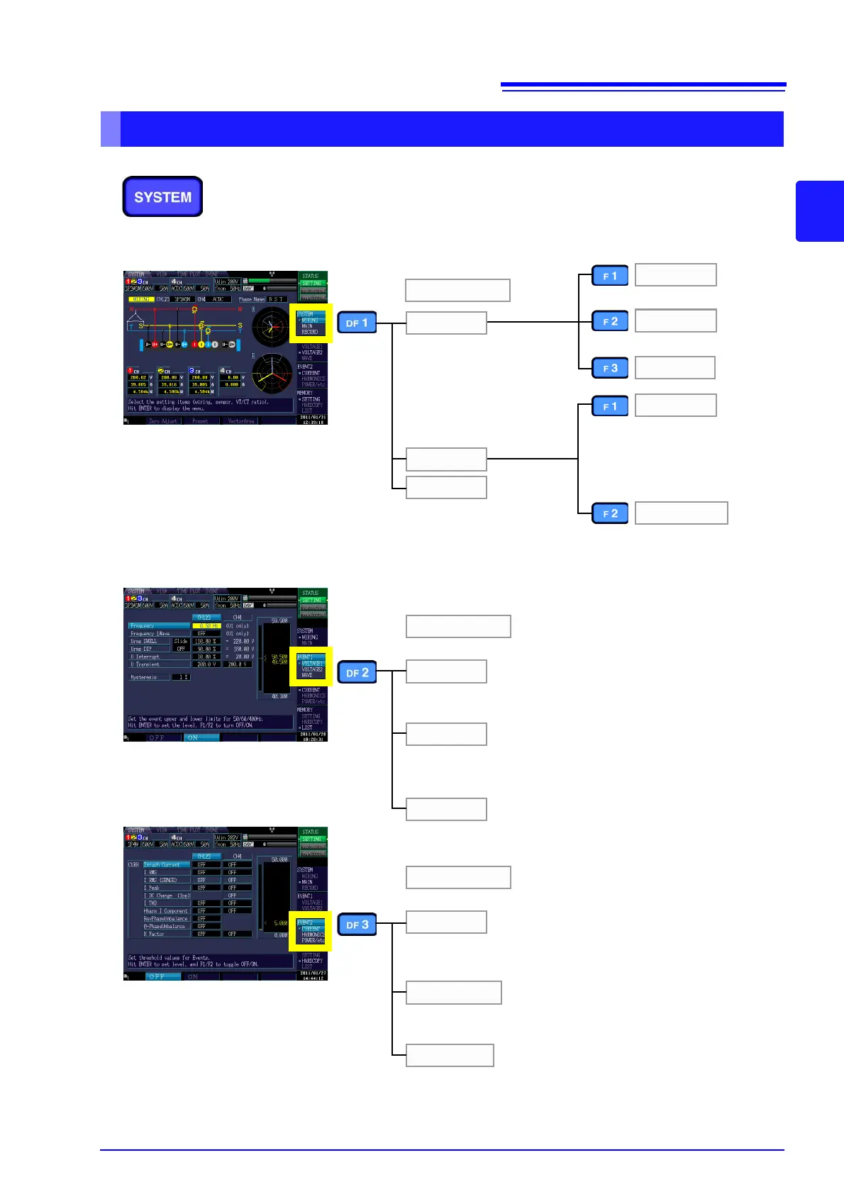
The [SYSTEM] screen is used to configure various instrument
settings.
Press the SYSTEM key to display the [SYSTEM] screen. The
screen can be changed with the DF keys.
Configures the connection,
clamp sensor, VT ratio, and
CT ratio settings. (This
screen is always displayed
after the instrument is turned
on.)
See: Chapter 4 (p.37)
VOLTAGE1
VOLTAGE2
WAVE
WIRING
MAIN
RECORD
SYSTEM
MEASURE
HARDWARE
Zero Adjust
Preset
VectorArea
Configures the recording,
TIMEPLOT interval, real-
time control, and repeated
recording settings.
See: 5.2 (p.58) to 5.3 (p.61)
Configures the connection,
clamp sensor, VT ratio, CT ratio,
current range, event, and TIME-
PLOT settings.
See: 5.1 (p.55)
Configures the display lan-
guage, screen color, clock, ex-
ternal output, RS-connected
device, beep, LCD backlight,
and LAN settings. Resets the
system.
See: 5.4 (p.64)
EVENT1
Configures the frequency, swell, dip, interruption, transient
threshold, and hysteresis settings.
Configures the RMS voltage, waveform peak, DC fluctuation,
harmonic distortion factor, high-order harmonic component, and
unbalance factor threshold settings.
See: 5.5 (p.66)
Configures the threshold settings for generating events with the
voltage waveform.
CURRENT
HARMONICS
POWER/etc
EVENT2
Configures the inrush current, RMS current, waveform peak, DC
fluctuation, harmonic distortion factor, high-order harmonic com-
ponent, unbalance factor, and K factor threshold settings.
Configures the threshold settings for 0- to 50-order harmonics
(voltage, current, power, phase).
See: 5.5 (p.66)
Configures the active power, reactive power, apparent power,
power factor threshold, timer event, external event, and continu-
ous event settings.
See: 4.7 (p.50)
See: 4.1 (p.37)