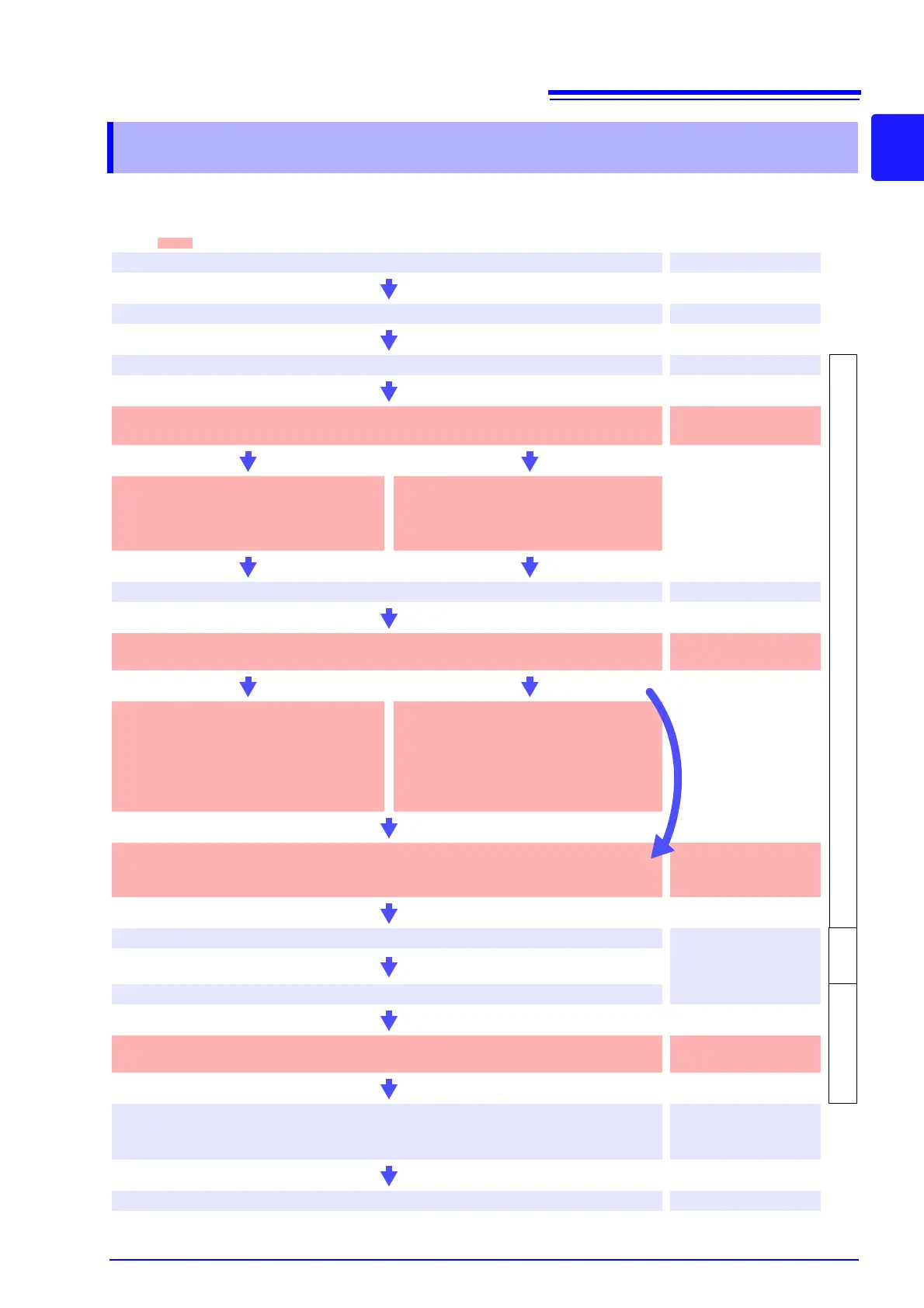
Note: shaded areas indicate settings configured on the instrument's screen.
Perform the pre-measurement inspection.
3.3 (p.31)
PW3198
operating state
Connect the AC adapter, voltage cords, and current clamps.
3.4 (p.32) to 3.7 (p.34)
Turn on the instrument.
3.8 (p.36)
[SETTING]
Perform zero adjustment after allowing the instrument to warm up for 30
minutes.
4.1 (p.37)
Configure initial settings.
Configure connection and clamp sensor
settings.
See: 4.3 (p.39)
Load a settings file (settings data).
Load a settings file from the SD memory
card.
See: 9.7 (p.146)
Connect to the measurement line.
4.5 (p.46)
Verify connections.
Note: If waveforms, measured values, or vector diagrams appear incorrect, reconnect the lines.
4.6 (p.48)
9.7 (p.146)
Configure settings using quick
setup.
Select quick setup and configure the con-
nection, clamp sensor, VT and CT, and
TIMEPLOT interval settings.
See: 4.7 (p.50)
Configure the settings as desired.
Set thresholds and other values as desired.
Settings can be configured as desired even
after using quick setup functionality.
See: Chapter 5 (p.55)
Verify settings, event count, and memory capacity.
Note: If waveforms or settings appear incorrect, or if the event count is unusually high,
change the settings.
4.8 (p.53)
Start recording.
"Starting and Stopping
Recording" (p.14)
[RECOR
DING]
Stop recording.
[ANALYZING]
Check and analyze measurement data.
(Data can also be checked while recording is in progress.)
Chapter 6 (p.75) to
Chapter 8 (p.119)
Disconnect the voltage cords and clamp sensors from the measurement
line and turn off the instrument.
(The display data will be erased. It cannot be redisplayed.)
3.8 (p.36)
Analyze the data on a computer using the computer application.
Chapter 12 (p.155)
See:
If you have loaded a
settings file
(settings data)