Appendix 7 Unstable Measured Values
A19
Appendix
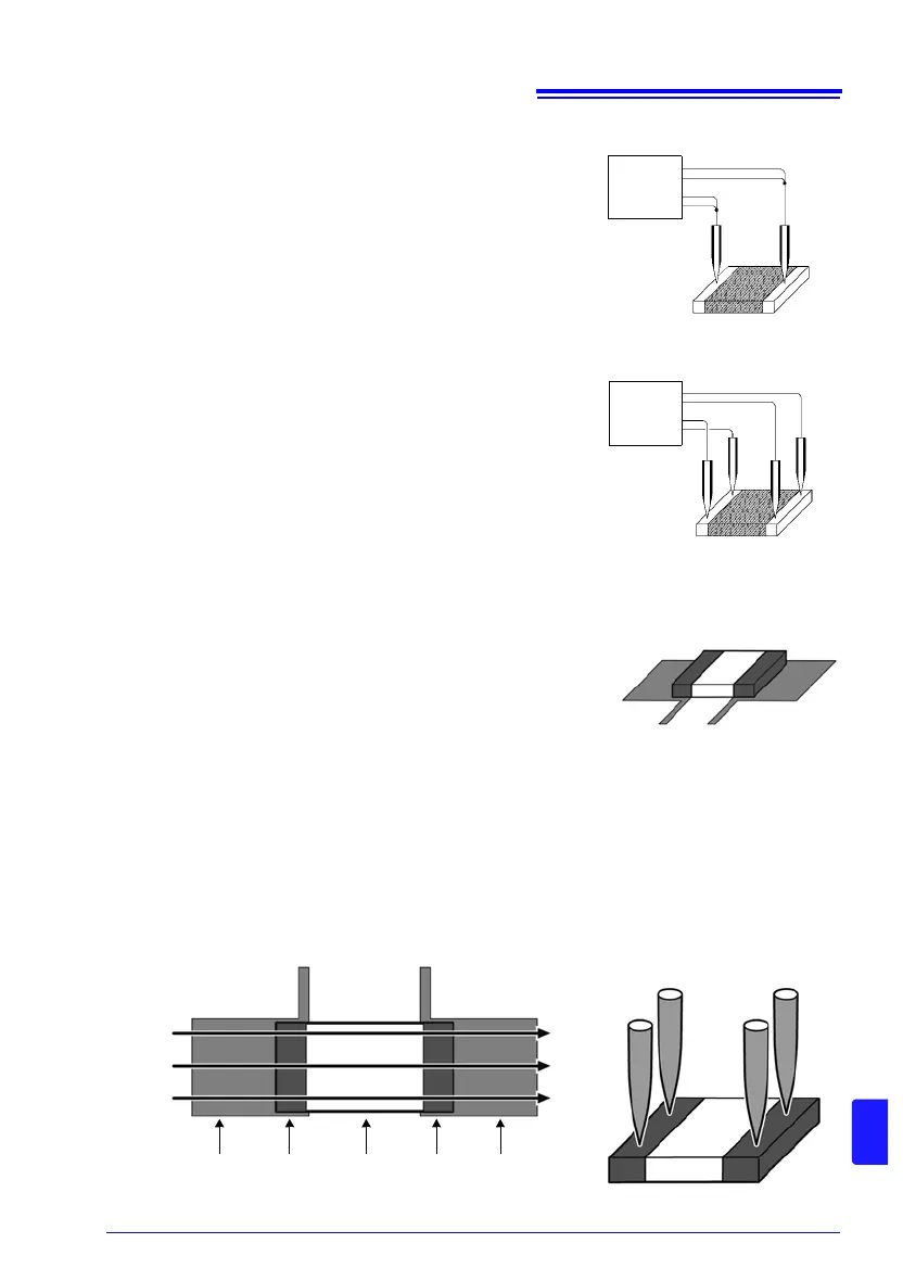
(9) Non-Four-Terminal Measurements
The four-terminal method requires that four probes be con-
nected to the measurement target.
By measuring as shown in Fig.12, the measured resistance
includes that of the contacts between the probes and mea-
surement target. Typical contact resistance is several mil-
liohm with gold plating, and several tens of milliohm with
nickel plating. With measured values of several k this
would not seem to be a problem, but if a probe tip is oxidized
or dirty, contact resistance on the order of a k is not
unusual.
To maximize the opportunity for accurate measurement,
separate the four probes so that they make contact with the
measurement target as shown in Fig. 13.
(10) Measurement of current sensing resistors (shunt resistors)
When mounting a two-terminal type current sensing resistor
on a printed circuit board, separate the current and voltage
detection wires as shown in Fig. 14 in order to avoid the
effects of wiring resistance. To ensure that the current will
flow evenly to the sensing resistor, it is necessary to use the
same width for the current wire as the electrode and to avoid
bending the wire near the electrode (see Fig. 15). When
testing the current sensing resistor, wire probes are gener-
ally used (see Fig. 16). In this case, the measurement current will gradually expand inside
the current sensing resistor from the point of application (SOURCE B) and flow back again
to the probe point (SOURCE A) (see Fig. 17). Current density is high at the current applica-
tion points (SOURCE A, SOURCE B), and placing the voltage terminals (SENSE A,
SENSE B) near them will yield resistance values that tend to be higher than the actual
mounted value (see Fig. 18).
Figure 12. Two-Terminal
Measurement
Figure 13. Four-Terminal
Measurement
SOURCE A
SENSE A
SENSE B
SOURCE B
SOURCE A
SENSE A
SENSE B
SOURCE B
Figure. 14A Current Sensing
Resistor mounted on a
Printed Circuit Board
Figure. 15 Current Flow in the Mounted State
Figure. 16 Probing in the Test State
Voltage detection Voltage detection
Conductor
pattern
Electrode Resistor Electrode
Current
Conductor
pattern