Appendix 17 Rack Mounting
A35
Appendix
By removing the screws on the sides, this instrument can be installed in a rack mounting
plate.
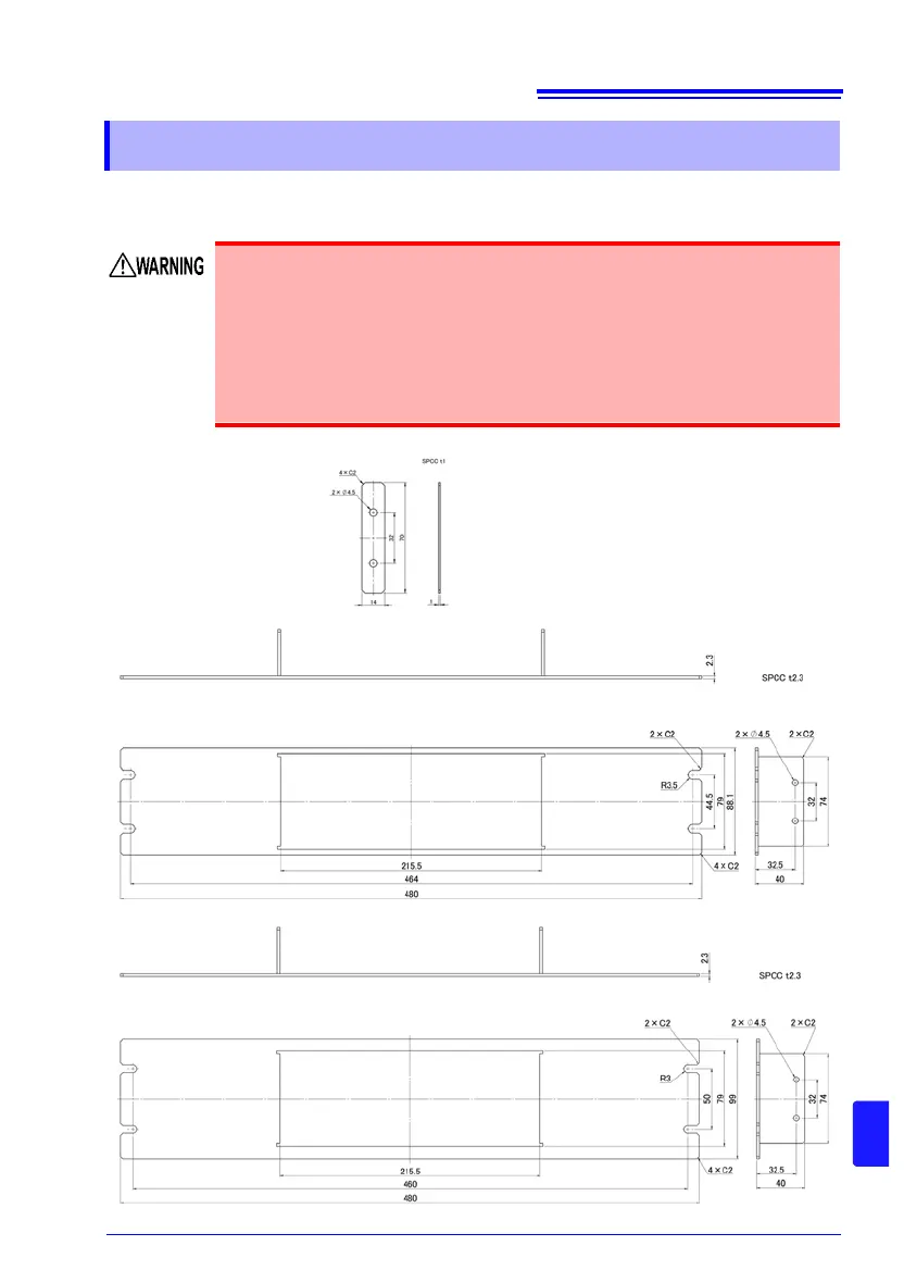
Rack Mounting Plate Template Diagram and Installation Procedure
Appendix 17 Rack Mounting
Observe the following precautions regarding the mounting screws to
avoid instrument damage and electric shock accidents.
• When installing the Rack Mounting Plate, the screws must not intrude
more than 3.5 mm into either side of the instrument.
• When removing the Rack Mounting Plate to return the instrument to
stand-alone use, replace the same screws that were installed origi-
nally. (Feet: M3 x 6 mm, Sides: M4 x 6 mm)
Rack Mounting Plate (JIS)
Rack Mounting Plate (EIA)
Spacer (Two Required)