8.1 About the Multiplexer
145
8
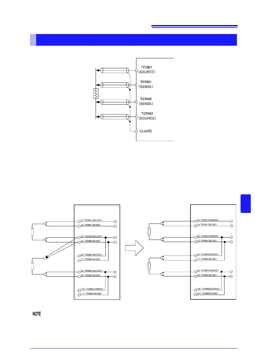
• Connect the multiplexer and measurement target as shown in the following diagram.
• Use shielded wires in the cables connected to the multiplexer connectors. Failure to do
so may cause measured values to be unstable due to the effects of noise.
• Connect cable shielding to the GUARD pin.
See: "Appendix 13 Making Your Own Measurement Leads, Making Connections to the Multiplexer"
(p. A29)
To allow separate measurement targets to be connected on a 1-to-1 basis, multiple pins
may have the same functions.
(Connection Examples)
Connections and measurements cannot span different multiplexer units.
Example of unsupported measurement
Between Unit 1 TERM 1 and Unit 2 TERM 2
About multiplexer wiring
It is possible to use wiring like this.
Z3003
(Pin no.) Function
Z3003
(Pin no.) Function