Appendix 1 Block Diagram
A1
Appendix
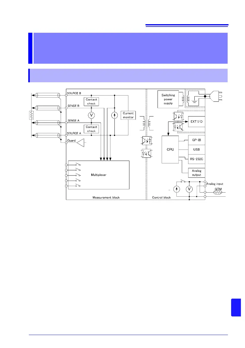
• Constant current (determined by the measurement range) is applied between the
SOURCE B and SOURCE A terminals while voltage is measured between the SENSE B
and SENSE A terminals. The resistance value is obtained by dividing the measured volt-
age (B) by the constant current flow (A).
• The effects of large offset voltages such as from thermal EMF can be reduced by current
flowing in the positive and negative directions (A).
• The low-noise voltmeter can perform stable measurement, even with an integration time
of 0.3 ms (B).
• When measurement starts, the contact check circuit (C) and constant current monitor (D)
are activated to monitor for fault conditions while measuring.
• The instrument incorporates a built-in temperature measurement circuit that can be used
to correct resistance measured values according to the temperature when measuring a
target that exhibits a high level of temperature dependence.
By separating the temperature measurement circuit from the constant current source, it is
possible to connect thermometers with analog output (E).
•
The high-speed CPU (
F
) provides ultra-high-speed measurements and fast system response.
• Immunity from electrical noise is provided by isolation between the Measurement and
Control blocks (G).
• The auto-ranging 100-to-240 V switching power supply (H) can provide stable measure-
ments even in poor power quality environments.
Appendix
Appendix 1 Block Diagram