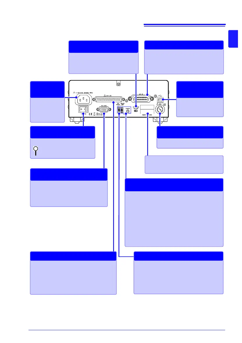
RS-232C connector
• Connect to a computer, PLC, or other
device (p.224).
• Connect to a printer (p.237).
RS-232C Communications
Printer Output
Power Inlet
Connect the sup-
plied power cord
(p. 35).
Connecting
the Power
Cord
Manufacturer's Serial Number
Do not remove this label, as it is required
for product support.
Fuse holder (p.300)
Replacing the
Measurement Fuse
Main power switch (p.43)
: Main power off
: Main power on
Turning the Main Power
On and Off
EXT I/O connector
Connect when controlling the instrument with
a PLC, I/O board, or other equipment to allow
measurement to be started and measured
values and comparator results to be acquired
(p.175).
External Control
USB jack
Connect to a computer
(p. 221).
Sending and
Receiving Data
via USB
EXT I/O NPN/PNP switch
Left : Current sink (NPN)
Right: Current source (PNP)
Switching between
NPN and PNP
TEMP.SENSOR jack/
TEMP.ANALOG INPUT terminal block
Connect the Z2001 Temperature Sensor or ther-
mometer with analog output when using temperature
correction or temperature conversion. (p.37)
Connect the Z2001 to the TEMP.SENSOR jack on
the right. Connect analog voltage output from a radi-
ation thermometer or a shunt resistor for analog cur-
rent output from a radiation thermometer to the
TEMP.ANALOG INPUT terminal block.
Correcting Temperature
Converting Temperature
D/A OUTPUT terminal block
The D/A OUTPUT terminal block outputs resis-
tance values as a voltage signal. (Connect a de-
vice that can accept voltage input, for example
a Memory HiCorder.) (p.173)
D/A Output
RM3545-01
GP-IB Connector
(RM3545-01 only)
Connect to a computer, or other device
(p.228)
GP-IB Communications