32
Installation GRS103
Release
01
03/2022
5.4 Management interfaces
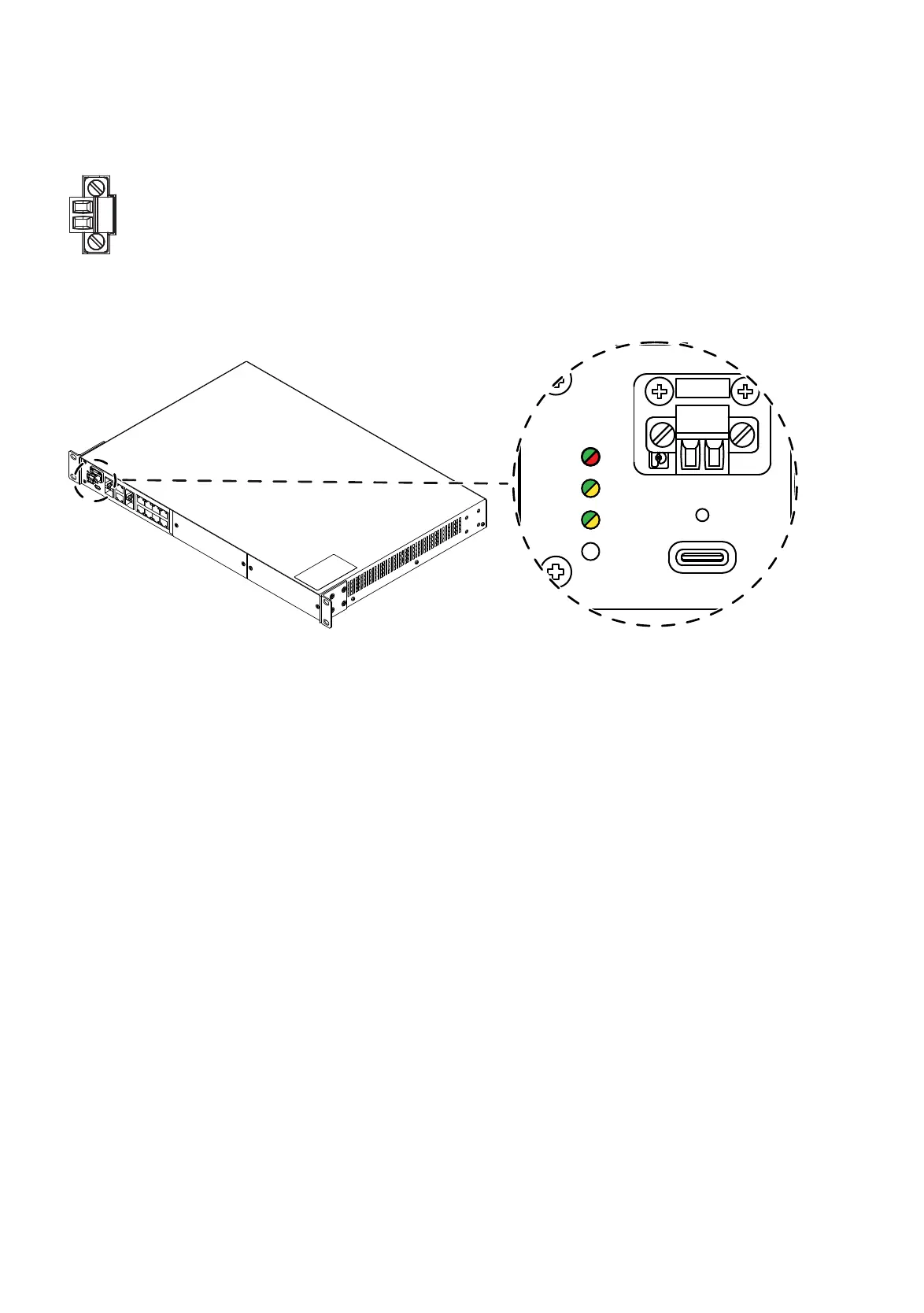
5.4.1 Signal contact
Figure 12: Signal contact: 2-pin terminal block with screw locking casing
Figure 13: Signal contact: 2-pin terminal block with screw lock; position on the device
The signal contact is a potential-free relay contact. When the device is not
connected to a power supply, the signal contact is open.
The potential-free signal contact (relay contact, closed circuit) reports
through a break in contact:
The detected failure of at least one of the two supply voltages
(supply voltage 1 or 2 is below the threshold value).
A detected continuous malfunction in the device.
The detected defective link status of at least one port. The link state can
be masked for each port in the graphic user interface. In delivery state,.
link monitoring is inactive.
Exceeding or falling below the set temperature threshold values.
Removal of the ACA22.
Connect the signal contact via a 2-pin terminal block with screw lock.
The signal contact (“Relay“, pin assignment of terminal block
see figure 24) is used to monitor the device function, and thus supports
remote diagnostics. You can specify the type of function monitoring in the
management.
You can use the Management to set the signal contact manually and thus
control external devices.