4 Electrical wiring
132
SMGB0077 rev.0 - 01/2013
Test runs
C A U T I O N
• Be careful during the test runs, as some of the safety functions remain disabled: the units operate for two
hours without switching off via the thermostat. The three-minute compressor protection is not enabled during
the test.
• Secure the rubber bushes to the panel using adhesive when the outdoor unit ducts are not used.
• The compressor remains at a standstill during forced stoppage.
4.1.3 Electrical connection of RCIM units
Work prior to the electrical connection
1 Turn off the power supply switches before starting work and t the appropriate locks and safety warnings.
2 Wait 5 minutes after turning off the power supply switches.
3 Check that the fans on the indoor and outdoor units are at a standstill before starting work.
N O T E
Theelectricalpowerfortheunitmustinvolveaspecicpowerline,withanexclusivepowercontrolswitchand
residual current breaker, installed in line with local or national safety regulations.
Check that the electrical power line has enough capacity to supply the unit. Its length, the cable diameter and their
protection (sleeve or jacket) must be appropriate for the unit.
For further information, always consider the current regulations in the country where the unit is to be installed.
C A U T I O N
Riskofre:cablesmustnevertouchtherefrigerantpipes,printedcircuitboards(PCB),sharpedgesorelectrical
components inside the unit to avoid damaging them.
Loose connection terminals may lead to cable and terminal overheating. The unit may operate incorrectly, leading
toariskofre.Checkthatthecablesarermlysecuredtotheconnectionterminals.
Electrical connection
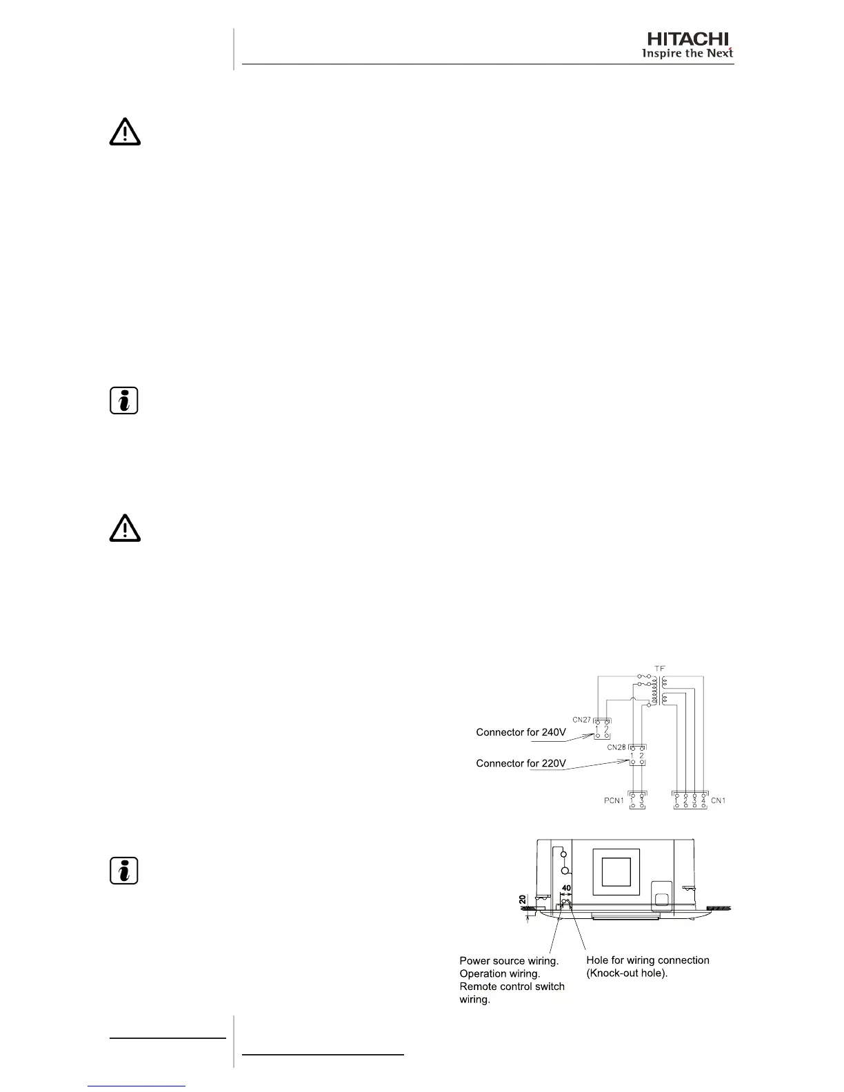
Check that the power supply for the RCIM indoor unit is 220 - 240 V.
If not, replace connectors CN27 and CN28 of the TF transformers
in the electrical box.
Make the connection between the indoor unit and the air panel.
N O T E
• To prevent the screws from falling from the terminal box,
do not remove them completely, hold onto the terminal
and check that the screw is secure through the hole in the
terminal.
• Use the following screws for the terminal box:
- M4 screw for the power supply.
- M3.5 screw for the operating line.
 Loading...

