2 Unit installation
44
SMGB0077 rev.0 - 01/2013
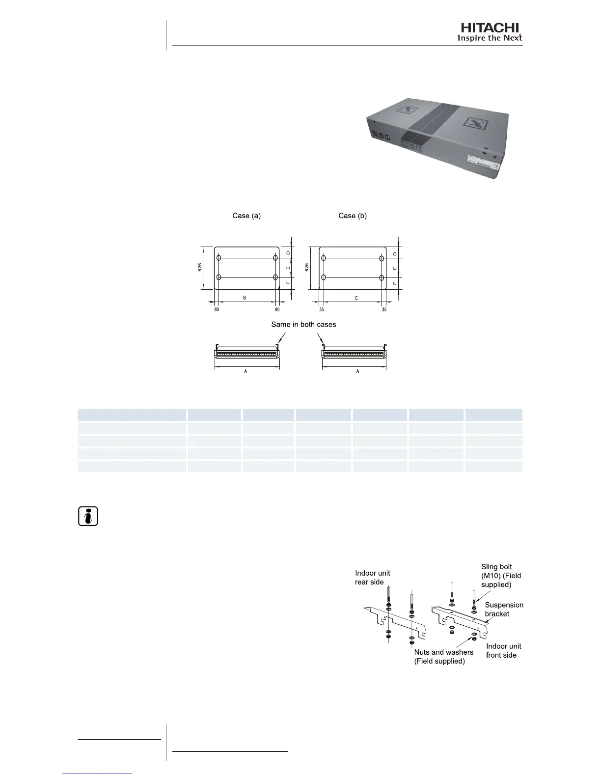
2.4.3 Suspension bracket installation
Cut out the printed pattern on the inside of the unit’s cardboard
packaging and follow the instructions printed on it.
The following information is also included on the pattern:
1 Separation of the sling bolt for installation positions (a) and (b).
2 Positions of the holes for the refrigerant pipes.
3 Positions of the holes for the drain pipes.
The suspension bracket can be hung in two positions:
Model A B C D E F
RPC-2.0FSN2E 1094 920 1010 150 220 255
RPC-(2.5/3.0)FSN2E 1314 1140 1230 150 220 255
RPC-4.0FSN2E 1314 1140 1230 110 280 235
RPC-(5.0/6.0)FSN2E 1574 1400 1490 110 280 235
Select the suspension bracket system in line with installation requirements.
N O T E
Installation position (a) is recommended for a partially hidden installation.
Fit the suspension brackets on the sling bolts or the anchor bolts
and securing using the nuts and washers supplied.
Apply a thread-locking product to the bolts and nuts to prevent
them from loosening. Otherwise, abnormal noise may be caused
by mechanical vibrations and the indoor unit may become loose.
 Loading...

