5 Control system
184
SMGB0077 rev.0 - 01/2013
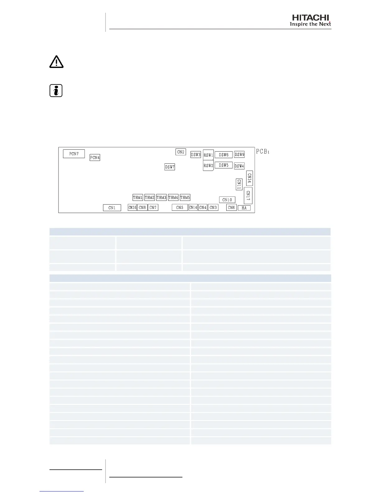
5.1.1 Printed circuit boards for RCI-FSN3 indoor units
C A U T I O N
Turn off the power supply before setting the DIP switches. If not, the settings will not be valid.
N O T E
• Thesymbol“■”indicatesthepositionoftheDIPswitches.Theguresshowthesettingbeforetransmission
or after selection.
• Ifthe“■”markisnotdisplayed,thisindicatesthatthepositionofthepinisnotaffected.
The indoor unit PCB operates with ve types of DIP switches and two rotary switches. The position is as follows:
LED indicator
LED1 Red
This LED indicates the transmission status between the indoor unit
and the remote control.
LED3 Yellow
This LED indicates the transmission status between the indoor unit
and the outdoor unit.
LED4 Red PCB power supply
Connector indication
PCN4 Not used
PCN7 Terminal board 1
THM1 Air inlet thermistor
THM2 Air outlet thermistor
THM3 Freeze protection thermistor
THM4 Not used
THM5 Gas piping thermistor
CN1 Motor for indoor fan
CN2 Terminal board 2
CN3 Not used
CN4 Not used
CN5 Not used
CN6 Not used
CN7 Not used
CN8 Not used
CN10 Air panel PCB
CN11 Micro-computer control expansion valve
CN14 Float switch
CN17 Air panel motor for automatic swing louver
CN34 Not used
 Loading...

