5 Control system
189
5
SMGB0077 rev.0 - 01/2013
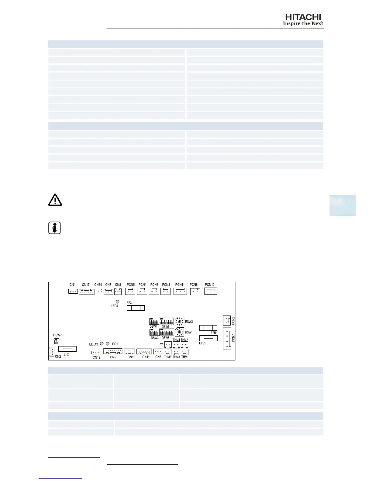
Connector indication
CN8 Optional output functions
CN11 Expansion valve control
CN14 Float switch
CN17 Swing louver motor 4
CN201 PCB1 connection
EFS1 PCB2 fuse
EFR1 PCB2 fuse
EF1 PCB1 fuse
EF4 PCB1 fuse
Switch indication
DSW3 Capacity code
DSW4 Unit model code
DSW5, RSW2 Refrigerant cycle number
DSW7 Fuse re-establishing
DWS6, RSW1 Indoor unit number settings
5.1.5 Printed circuit board for RPC, RPF(I), units
C A U T I O N
Turn off the power supply before setting the DIP switches. If not, the settings will not be valid.
N O T E
• Thesymbol“■”indicatesthepositionoftheDIPswitches.Theguresshowthesettingbeforetransmission
or after selection.
• Ifthe“■”markisnotdisplayed,thisindicatesthatthepositionofthepinisnotaffected.
The indoor unit PCB operates with four types of DIP switches, a slide switch and a rotary switch. The position is as follows:
LED indicator
LED1 Red
This LED indicates the transmission status between the indoor unit
and the remote control.
LED3 Yellow
This LED indicates the transmission status between the indoor unit
and the outdoor unit.
LED4 Green PCB power supply
Connector indication
PCN1 220 V transformer
PCN2 Indoor fan motor internal thermostat
 Loading...

