5 Control system
198
SMGB0077 rev.0 - 01/2013
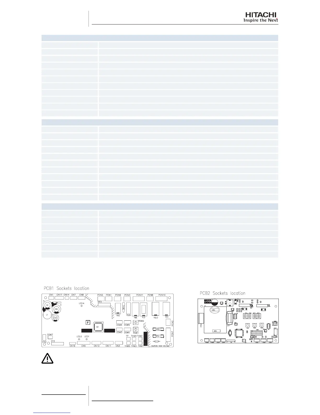
PCB1 Connector indication
CN8 Not used
CN10 Not used
CN11 Expansion valve
CN14 Float switch
CN17 Not used
CN19 Not used
EFR1 PCB1 fuse
EFS1 PCB1 fuse
EF2 Not used
EF3 PCB1 fuse
TP Not used
PCB2 Connector indication
PCN1 TB1 and PCB1
THM1 Coil inlet thermistor
THM2 Coil outlet thermistor
CN1 TB1 and PCB1
CN2 CO2 sensor 4-20 mA
CN3 CO2 sensor 0-10 V
CN4 CO2 sensor ON/OFF
CN5 Motor for fan 1
CN6 Motor for fan 2
EF1 PCB2 fuse
TP Not used
Switch indication
DSW1 Not used
DSW2 Not used
DSW3 Capacity code
DSW4 Unit model code
DSW5, RSW2 Refrigerant cycle number
DWS6, RSW1 Indoor unit number settings
DSW7 Fuse re-establishing
5.1.10 Printed circuit board for DX-Interface complementary systems
Dips switches location is the following:
C A U T I O N
BeforesettingDIPswitches,rstlyturnoffpowersourceandsetthepositionofthedipsswitches.Iftheswitches
are set without turning off the power source, the contents of the setting are invalid.
 Loading...

