5 Control system
188
SMGB0077 rev.0 - 01/2013
5.1.4 Printed circuit boards for RCD indoor units
C A U T I O N
Turn off the power supply before setting the DIP switches. If not, the settings will not be valid.
N O T E
• Thesymbol“■”indicatesthepositionoftheDIPswitches.Theguresshowthesettingbeforetransmission
or after selection.
• Ifthe■markisnotdisplayed,thisindicatesthatthepositionofthepinisnotaffected.
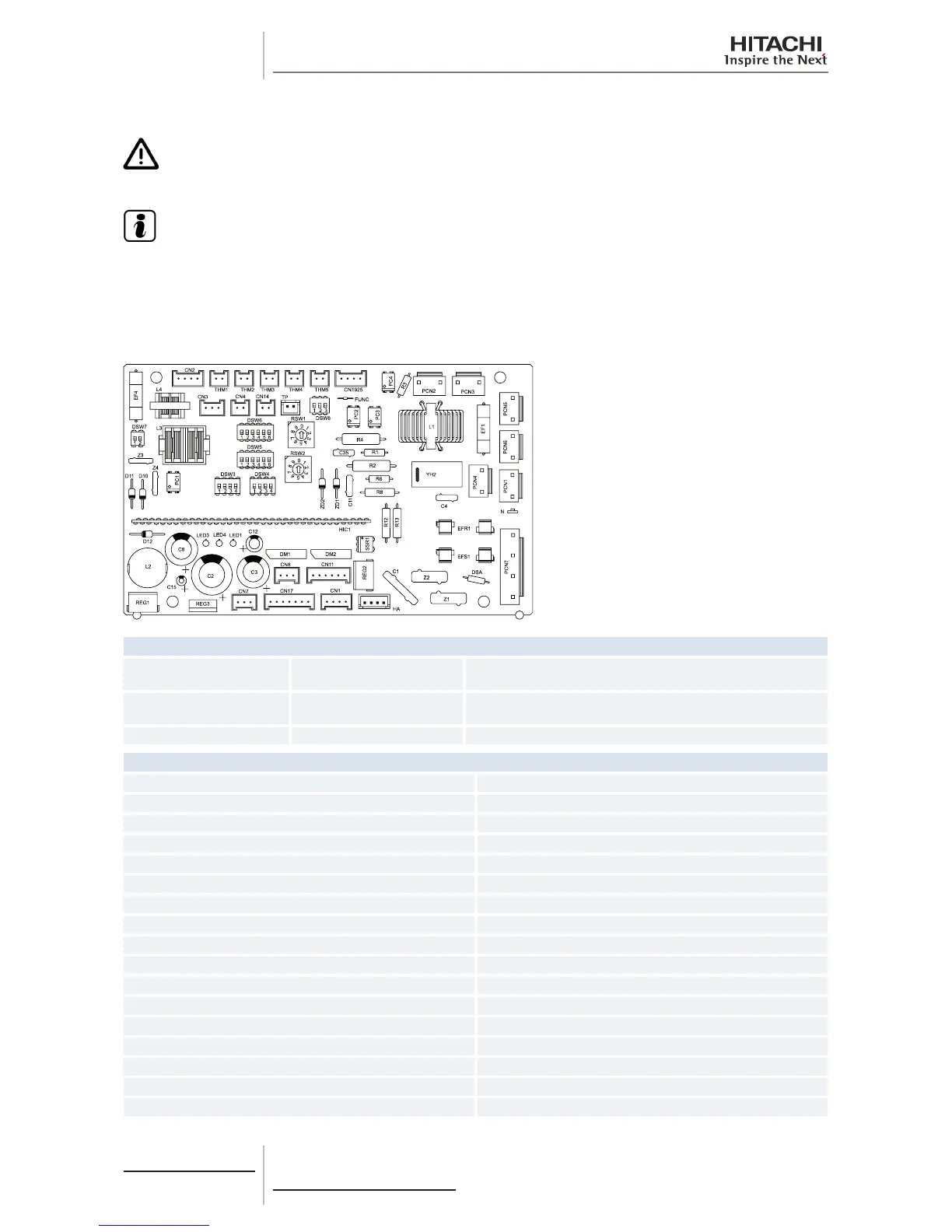
The indoor unit PCB operates with ve types of DIP switches and two rotary switches. The position is as follows:
LED indicator
LED1 Red
This LED indicates the transmission status between the indoor unit
and the remote control.
LED3 Yellow
This LED indicates the transmission status between the indoor unit
and the outdoor unit.
LED4 Red PCB power supply
Connector indication
PCN1 220 V transformer
PCN5 Electric heater for dew protection
PCN6 Drain pump motor
PCN7 Power supply (1-R, 3-S)
PCN201 Power supply (1-R, 3-S)
PCN202 Power supply (1-R, 3-S)
PCN203 DC motor control
THM1 Air inlet thermistor
THM2 Air outlet thermistor
THM3 Liquid pipe thermistor
THM4 Remote thermistor
THM5 Gas pipe thermistor
CN1 Transformer (pins 1-2: 17.3 V/pins 3-4: 20.8 V)
CN2 Outdoor unit H-LINK II control circuit
CN3 Optional input functions
CN4 Not used
CN7 Optional output functions
 Loading...

