(*1): If external duty control is selected (switch 1-2), check the proper selection for the duty signal (switch 3-4).
(*2): The thermo ON/OFF control can be driven externally by an input signal connected to the CN3 socket of the
PCB1. The switch 6 of DSW1 in PCB2 must be switched on, then the input “i1” of CN3 is automatically set for
thermo ON/OFF control. The setting of input “i2” is kept as set on the remote controller.
C A U T I O N
If there is an indoor unit connected in the same RCS line as DX-Interface EXV-(2.0-10.0)E1 or KPI-(E/H/X)3E, then
pin 7 must be ON to disable the power supply to RCS line. If there is no indoor unit connected to the same RCS
line but there are more than one DX-Interface EXV-(2.0-10.0)E1 or KPI-(E/H/X)3E, then only one DX-Interface EXV-
(2.0-10.0)E1 or KPI-(E/H/X)3E should have pin 7 OFF while all other units must have pin 7 set to ON. Failure to
perform this setting correctly will result in bad communication and can even cause physical damage to the PCB.
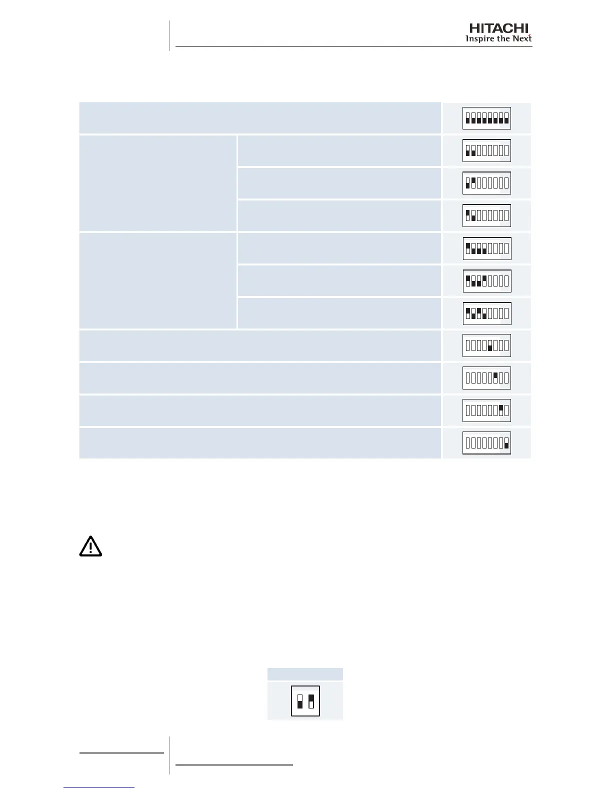
DSW2: End resistance
No setting is required.
All units
1 2
ON
 Loading...

