10 Servicing
383
10
SMGB0077 rev.0 - 01/2013
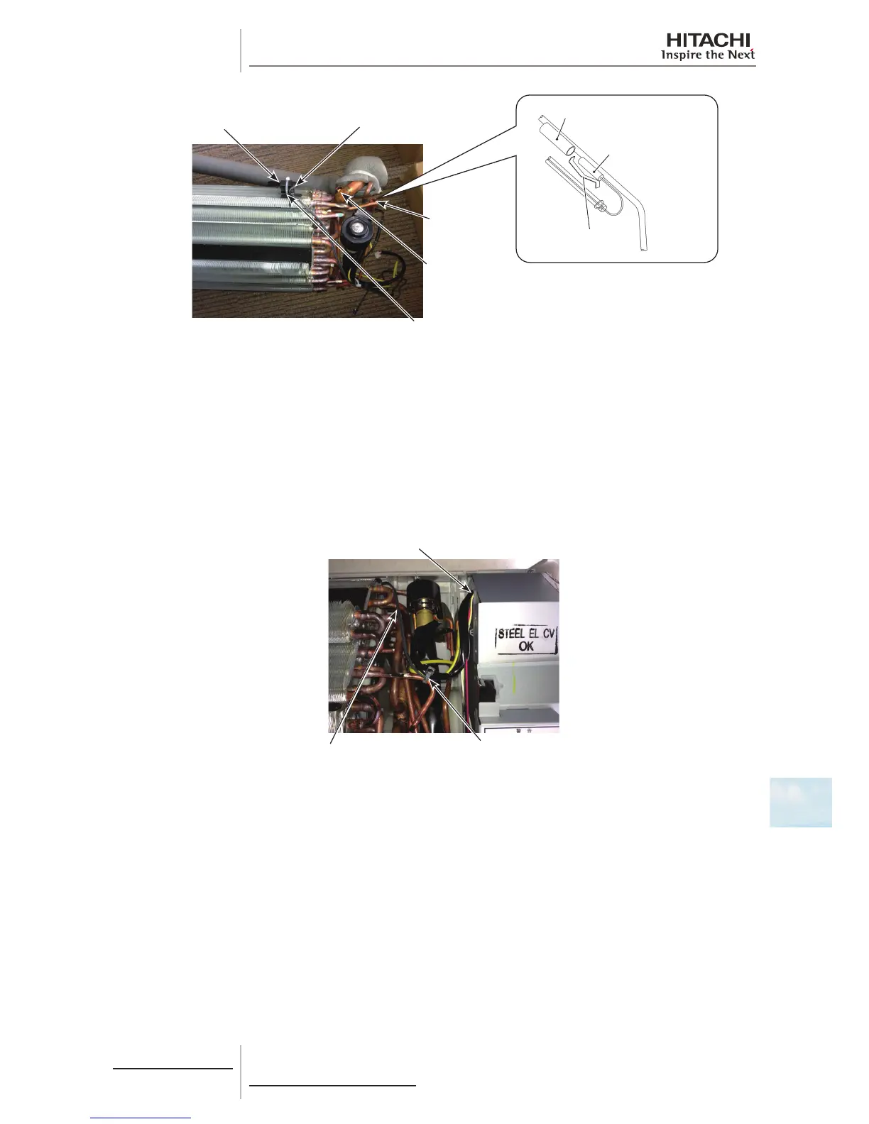
Inlet Air Thermistor
Rasin Component Fixing
Inlet Air Thermistor
Freeze
Protection
Thermistor
Gas Pipe
Thermistor
Plastic Band (B)
Freeze Protection
Thermistor
Termistor Pipe
Termo Clip
7 Removing Inlet Air Thermistor
a. The inlet air thermistor is clamped with one (1) plastic band (B) to the resin component for xing the thermistor
inserted into the sub heat exchanger ns. Remove the plastic band to remove the thermistor.
b. When attaching the inlet air thermistor, attach it to the resin component with the plastic band in the reverse procedure.
Take care during the work so that the wiring for the thermistor will not come into contact with metal edges of ns or
side plates of the heat exchanger.
c. After attaching the thermistor, clamp the wiring for the expansion valve, freeze protection thermistor, gas pipe
thermistor and suction air thermistor with one (1) plastic band.
and the expansion valve coil into the electriacal box from the wiring outlet at the upper side.
(The wiring for the expansion valve coil is not included when using the unit without expansion valve)
Fix the inlet air thermistor with the plastic band
so that the thermistor wire will not be loosened.
Clamp the wirings for the thermistors
(for inlet air, gas pipe and freeze protection),
and the expansion valve coil with the plastic band.
(The wiring for the expansion valve coil is not included
when using the unit without expansion valve)
8 Removing Outlet Air Thermistor
a. Remove the drain pan according to the item 2.1.7 “Removing Drain Pan.”
b. Remove the rubber bush and the ocked sheet xing the outlet air thermistor from the back side of the drain pan.
Then pull out the rubber bush from the drain pan.
c. When attaching the outlet air thermistor, attach the rubber bush and x the thermistor with the ocked sheet in the
reverse procedure.
 Loading...

