9 Servicing
RAS-(4-6)H(V)(R/N)(C/P)2E
SMGB0136 rev.0 - 07/2021
205
9
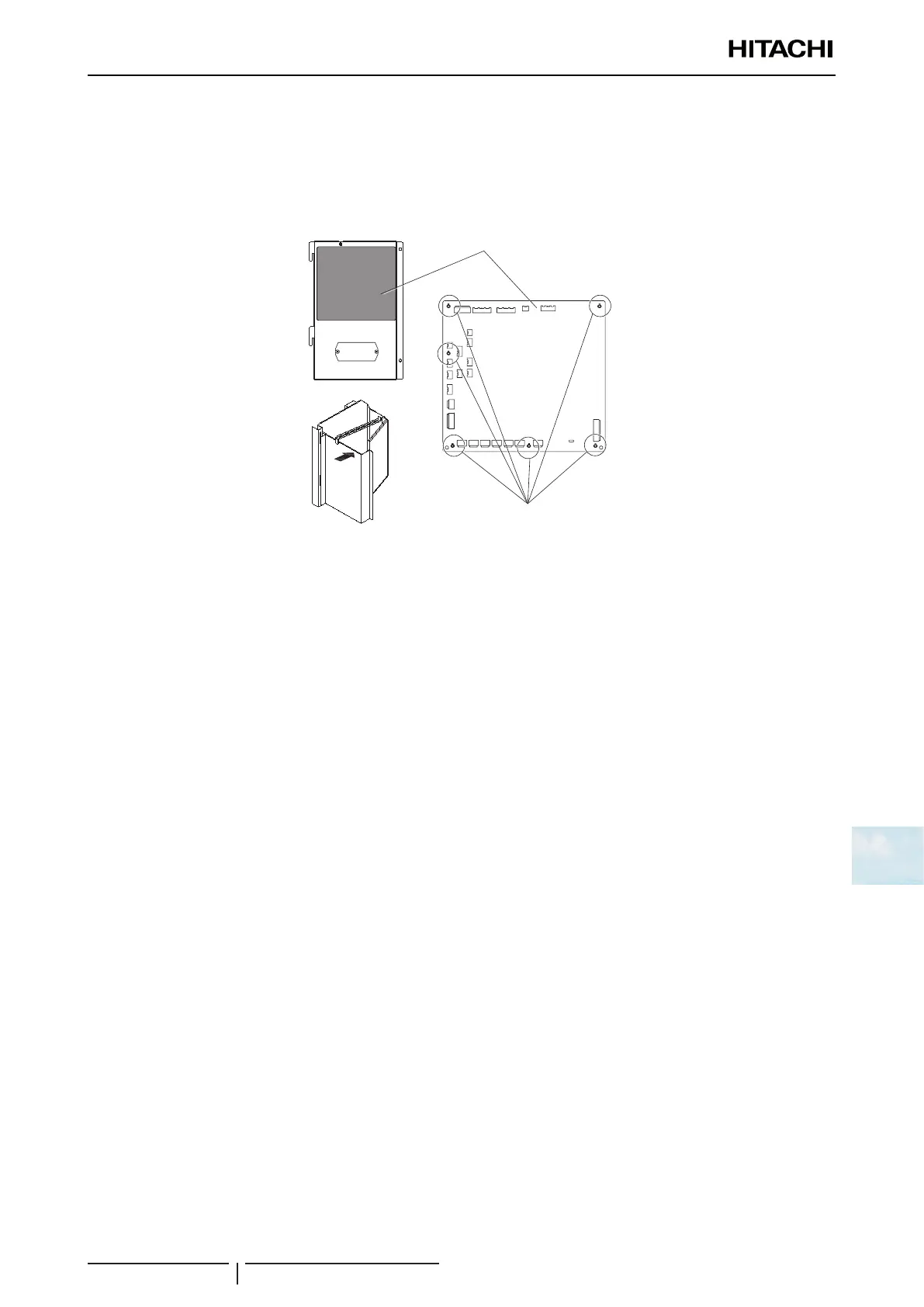
Disassembly / Assembly the control PCB (PCB1)
1 Disassembly the service cover according to the item “9.3.1Removingservicecover”.
2 Disconnect all the wiring connected to the control PCB.
3 Remove the 6 xing holders -2- and disassembly the control PCB -1-.
4 Assembly the new control PCB -1- and x it with 6 holders -2-.
2
1
5 Connect all the wiring connected to the control PCB as it was originally.
6 Assembly the service cover according to the item “9.3.1Removingservicecover”.
Disassembly / Assembly the Inverter module (PCB2)
1 Disassembly the upper cover according to the item “9.3.3Removinguppercover”.
2 Open the electrical box according to the item “Opening/ClosingElectricalbox(Pplate)”.
3 Disconnect all the wiring connected to the Inverter module.
- DCL1 (Reactor)
- DCL2 (Reactor)
- CN331 (NF)
- CN16 Aerial connector (compressor)
- PCN2 (pressure switch control)
- CN206 (PCB communication)
- R, S, T (NF)
4 Remove the 8 xing screws -2- and disassembly the control PCB -1-.
- Recommended the use of a exible screwdriver or if necessary, remove the PCB3 according to the item
“Disassembly/AssemblythePCB3” to improve the access to the right side screws.
5 Pull the Inverter and remove along with the plastic case and the radiation n.
6 Assembly the new control PCB -1- and x it with 8 screws -2-.