D2 Drive User Guide v1.8 5. Drive Configuration
HIWIN Mikrosystem Corp. 123
5.5.4. Extension I/O
For D2 drive with the extension I/O module, parameters shown in Table 5-11 can be used to
set the voltage level for each extension I/O pin.
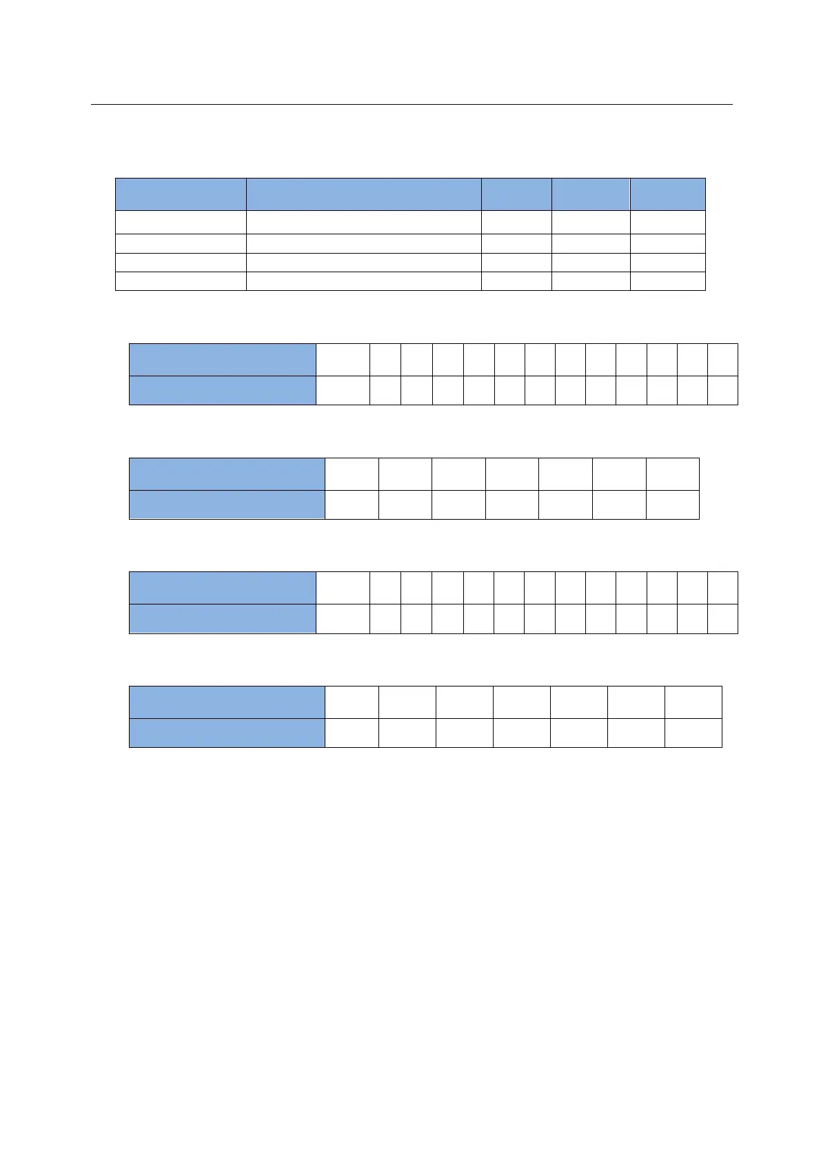
Table 5-11 Extension I/O parameters
Inputs on the extension I/O CN13
Outputs on the extension I/O CN13
Inputs on the extension I/O CN14
Outputs on the extension I/O CN14
(1) Configured relationship between External_Input_1 and CN13:
Bit No. of
External_Input_1
(2) Configured relationship between External_Output_1 and CN13:
Bit No. of
External_output_1
(3) Configured relationship between External_Input_2 and CN14:
Bit No. of
External_output_2
(4) Configured relationship between External_Output_2 and CN14:
Bit No. of
External_output_2
Example:
When DI 9 of CN13 (pin 22) is at the high level, DO 2 of CN13 (pin 3 and pin 4) outputs a
high-level signal.
#task/1;
_External_IOtest:
till(External_Input_1 & 0x0100 ); // Wait for DI 9 of CN13 to be high level.
External_Output_1 = 0x0002; // DO 2 of CN13 outputs a high-level signal.
ret;