D2 Drive User Guide v1.8 4. Wiring
HIWIN Mikrosystem Corp. 52
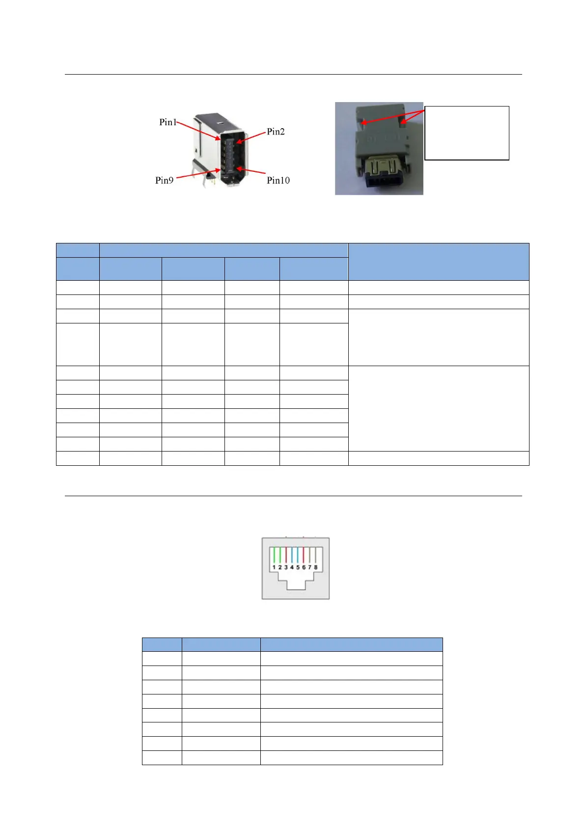
4.1.8. CN7 encoder
Press and pull clamps on both sides to remove CN7 connector.
Fig. 4-19
Table 4-9
Encoder power output of +5 Vdc
Digital ground and ground for +5 Vdc
17-bit incremental: timing output for
serial communication (MA+, MA-)
17-bit absolute and dual-loop
architecture: data transmission for
serial communication (PS+, PS-)
13-bit incremental: digital signal
transmission (A, /A, B, /B, Z, /Z)
17-bit incremental: data transmission
for serial communication (SL+, SL-)
Dual-loop architecture: digital signal
transmission (Connecting to linear
encoder)
4.1.9. CN8 EtherCAT communication
To connect with the EtherCAT module, the connector of network cable should have the
shielding protection.
Fig. 4-20 CN8 connector
Table 4-10 CN8 pin assignment
Positive terminal of data transmit
Negative terminal of data transmit
Positive terminal of data receive
Negative terminal of data receive
(a) SCR connector 10 pin (male)
(b) SCR connector 10PIN (female)
Press and pull
these clamps to
remove CN7
connector